When you have a new technology developing, especially one with such tremendous market potential as fiber optic communications, you get a large number of people and organizations entering the market. Many new ideas get proposed; some get developed and some become successful. But many more fail than succeed.
Success depends on several factors. The idea must provide a solution to a recognized problem. It must be practical and easy to implement. It must be economical. And it must be timely. Successful ideas pass all four criteria, but many miss one or more and fail.
In the time I have been involved with fiber optics, I’ve seen some major successes and a lot more failures. I’ve probably seen more than most because my company, FOTEC, made test equipment, and we sold to a lot of companies developing new products—especially connectors.
During the early days of fiber optics, there were many ideas about making connectors. Splicing was easily solved using an electric arc to fuse (weld) two fibers together for a permanent connection, but connectors were much more difficult. You needed to mate two fibers with low loss and reflectance, but the connector had to be durable enough to make and break connections many times while still having low loss. It needed to be stable over environmental changes such as temperature and humidity, and rugged enough to withstand typical handling.
In the beginning, connectors used many different techniques to connect two fibers: molded connector ferrules (AT&T Biconic, AMP Optimate), machined ferrules (SMA), bare fiber connectors like mechanical splices (Deutsch, TRW) and even a few expanded beam connectors.
The idea of an expanded beam connector was to use a lens to make the beam of light from the fiber bigger to ease the alignment between the connectors. Bigger beams of light also had another advantage; dust was smaller than the beam of light and was no longer a problem.
But expanded beam connectors were not easy to build. They required aligning a fiber with a tiny lens in the connector precisely to get low loss, which was exceedingly difficult, and even more so with single-mode fiber.
At the same time, in 1982, Eastman Kodak introduced the Disc camera, which used a tiny film size, 8 x 10 mm, compared to 24 x 36 mm for a 35-mm film camera. With the Disc camera, Kodak also pioneered molded lenses, a new technology.
Some engineers decided that this lens-molding technology could be used to solve the connection problem for fiber optics, especially with single-mode fiber. Kodak developed a molded collimating lens to the specifications of single-mode fiber and a plastic body to hold it, the fiber and the cable. They called it the Lamdek connector.
The termination process was complicated. The fiber was glued into a glass ferrule, polished and then glued to the flat backside of the lens. The alignment of the fiber and the lens was critical and needed to be done before the glue set on the lens. That required testing and was where I became involved.
FOTEC showed Kodak how to measure the power from the connector and how it peaked when the fiber was properly aligned. We also showed them how to measure the loss of two mated connectors. At that time, the Lamdek connector had a loss of about 1 dB with single-mode fiber, as good as any other connector available at the time.
Kodak contracted with FOTEC to develop a field kit to terminate and align the connectors. The kit was in a portable, briefcase-sized container. Production equipment was created and Kodak made a lot of patchcords to test the processes and equipment.
But in high tech, timing is everything. Just as Kodak was ready to introduce the Lamdek connector, Japanese companies NTT and NEC introduced connectors using ceramic ferrules that had average losses of less than 0.5 dB with single-mode fiber. Every other connector was rubbish in comparison!
The Lamdek connector project was canceled, but from FOTEC’s standpoint, there was a positive ending. The Lamdek connector worked great to couple the beam of light from a red helium-neon laser into a fiber. FOTEC had recently introduced the laser visual fault locator (VFL) that could use the Lamdek connector. We bought all the patchcords—I think we paid $1 each—and used them in our VFL for years.
Read this month’s online column to learn more about the different connector types tried in the early days of fiber optics.
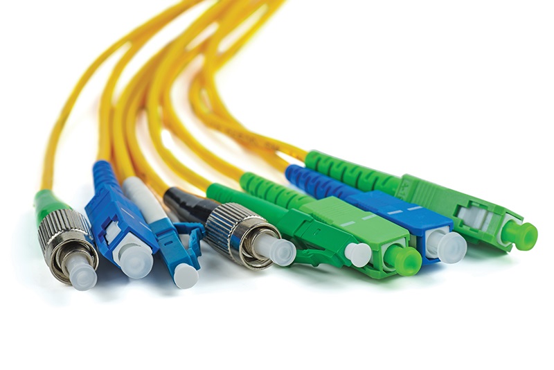
stock.adobe.com/Roman Ivaschenko
About The Author

HAYES is a VDV writer and educator and the president of the Fiber Optic Association. Find him at www.JimHayes.com.