Overview of NEC Article 430 and its scope
Article 430 in the National Electrical Code (NEC) covers motors, motor branch-circuit and feeder conductors and their protection, motor overload protection, motor control circuits, motor controllers, and motor control centers. Article 430 contains 14 parts, which is the second highest number or parts out of any article in the Code. Part I contains general requirements pertaining to motors, motor circuits and motor controllers. Some of the headings in Part I are Scope, Definitions, Ampacity and Motor Rating Determination, Marking on Motors and Multimotor Equipment, Marking on Controllers, Terminals, Motor Terminal Housings, Location of Motors, and Highest Rated or Smallest Rated Motor.
Motor circuit conductors and voltage applications
The sections in Part I include 430.1 through 430.18. Part II contains requirements for motor circuit conductors. The sections in Part II include 430.21 through 430.29. The provisions of Part II shall not apply to motor circuits rated over 1,000 volts (V), nominal. Provisions for motor circuits rated over 1,000V, nominal, are in Part XI.
Conductor sizing for continuous-duty motors
As stated in 430.21, the sections in Part II contain requirements necessary for sizing conductors so they are capable of carrying the motor current without overheating under the conditions specified. Conductors that supply a single motor used in a continuous-duty application shall have an ampacity of not less than 125% of the motor full-load current (FLC) rating, as determined by 430.6(A)(1), or not less than specified in 430.22(A) through (G) [430.22].
This requirement ensures that electrical contractors size conductors conservatively to prevent overheating and maintain NEC safety compliance.
The provision in 430.22 pertains to a single motor used in a continuous-duty application. Many, but not all motors are used in a continuous-duty application. The percentage used with this type of motor is the same percentage used when there is a continuous load, but don’t be tricked into thinking this section is talking about a motor being a continuous load.
Distinguishing continuous load vs. continuous duty
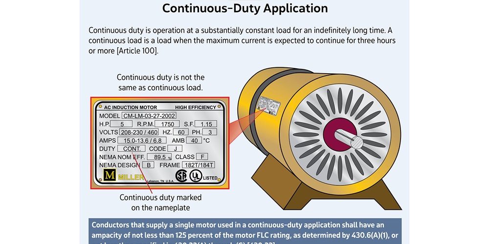
As defined in Article 100, a continuous load is one where the maximum current is expected to continue for three hours or more. There is no mention of a specific time period with continuous duty. The term continuous duty also is defined in Article 100 as operation at a substantially constant load for an indefinitely long time (see Figure 1).
Using FLC tables for conductor calculations
The specification for determining the minimum size conductors that supply a single motor used in a continuous-duty application is in 430.22. It would be easy to use the amps shown on the motor’s nameplate when sizing the conductors, but this would be a violation.
The NEC’s FLC tables provide standardized values across installations, ensuring consistency for inspections and long-term reliability.
This section says to use the FLC rating, as determined by 430.6(A)(1). This section says not to use the actual current marked on the motor’s nameplate when determining the ampacity needed for sizing conductors unless the motor is built for low speeds (less than 1,200 RPM) or high torques, or unless the motor is a multispeed motor.
Instead of using the amps on the motor’s nameplate, it is required to use the FLC values given in Table 430.247, Table 430.248, Table 430.249 and Table 430.250. These tables near the end of Article 430 show FLC in amperes for direct-current motors, single-phase alternating current motors, two-phase alternating current motors (4-wire), and three-phase alternating current motors. The conductors supplying a single motor are branch-circuit conductors. Using the FLC tables in Article 430 is not only necessary when calculating branch circuit conductors, the FLC tables are also necessary when calculating ampere ratings of switches, branch-circuit protection, feeder conductors, and feeder protection.
Example: 15-hp, 208V, three-phase motor calculation
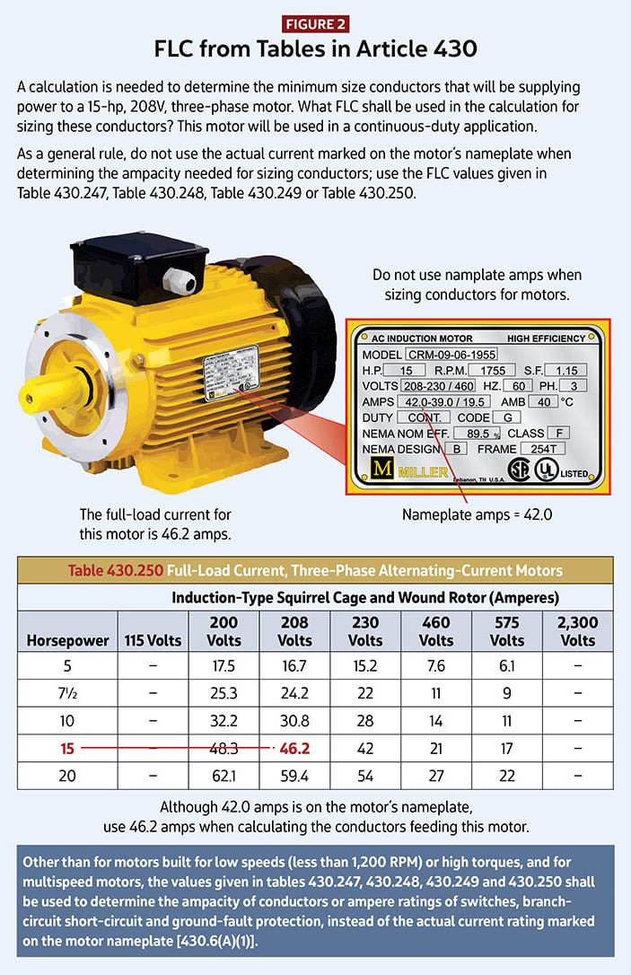
For example, a calculation is needed to determine the minimum size conductors that will be supplying power to a 15-horsepower (hp), 208V, three-phase motor. What is the FLC that shall be used in the calculation for sizing these conductors? This motor will be used in a continuous-duty application.
The motor’s nameplate shows this motor will draw 42.0 amperes (A) when the voltage at the motor will be 208V, three-phase. Although the nameplate shows 42.0A, do not use this number when calculating branch- circuit conductors. Since the motor in this example is three-phase, use Table 430.250. Under induction-type, squirrel cage, and wound rotor motors, find the 208V column. Follow down the 208V column and find the row with a 15-hp motor. The FLC for a 15-hp, 208V, three-phase motor is 46.2A. Although 42A is on the motor’s nameplate, it is required to use 46.2A when calculating branch-circuit conductors for this motor (see Figure 2).
The first step when sizing branch circuit conductors for a single motor used in a continuous-duty application is to find the FLC from either Table 430.247, Table 430.248, Table 430.249, or Table 430.250. The two tables used most often are Table 430.248 for single-phase alternating current motors and Table 430.250 for three-phase alternating current motors. The next step is to multiply the FLC by 125 percent.
Using Table 310.15(B)(16) to select a conductor
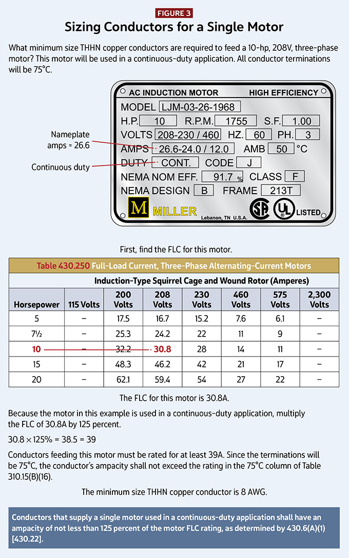
Finally, select a conductor from Table 310.15(B)(16). For example, what minimum size THHN copper conductors are required to feed a 10-hp, 208V, three-phase motor? This motor will be used in a continuous-duty application. The motor’s nameplate shows this motor will draw 26.6A when the voltage is 208V, three phase. All conductor terminations will be 75°C. First, find the full load current for this motor. Because this is a three-phase motor, look in Table 430.250 for the FLC. The FLC for a 10-hp, 208V, three-phase motor is 30.8A. Because the motor in this example is used in a continuous-duty application, multiply the FLC by 125 percent. The minimum ampacity for sizing the conductors supplying power to this motor is 39A (30.8 × 125 percent = 38.5 = 39).
Finally, select a copper conductor from Table 310.15(B)(16). Size 10 THHN copper conductors have an allowable ampacity of 40A as shown in the 90°C column in Table 310.15(B)(16), but the conductor’s ampacity shall not be selected from the 90°C column. Because of the provision in 110.14(C), the conductor’s ampacity shall not exceed the temperature rating of the terminations. Since the terminations in this example will be 75°C, the conductor’s ampacity shall not exceed the rating in the 75°C column of Table 310.15(B)(16). A 10 AWG conductor only has an allowable ampacity of 35A as shown in the 75°C column. The minimum size THHN copper conductors supplying power to a 10-hp, 208V, three-phase motor is 8 AWG (see Figure 3).
Other motor duty applications in 430.22
Many motors are used in a continuous-duty application, but not all. To size conductors that supply a single motor not used in a continuous-duty application, look at the other specifications in 430.22. Other motors covered here include: a DC motor operating from a rectified power supply; a multispeed motor; and a wye-start, delta-run connected motor. Section 430.22 also has a subsection for other than continuous-duty motors. Section 430.22(E) pertains to motors used in a short-time, intermittent, periodic and varying duty application. Although these four motor applications look like they could be the same, they are not the same.
Like the term continuous duty, the other four terms are also defined in Article 100. Short-time duty is defined as operation at a substantially constant load for a short and definite, specified time. Intermittent duty is operation for alternate intervals of (1) load and no load; or (2) load and rest; or (3) load, no load and rest. Periodic duty is intermittent operation in which the load conditions are regularly recurrent. Varying duty is operation at loads, and for intervals of time, both of which may be subject to wide variation. One way to confirm the duty application of the motor is to look at the nameplate on the motor. These motors shall have an ampacity of not less than the percentage of the motor nameplate current rating shown in Table 430.22(E), unless the authority having jurisdiction grants special permission for conductors of lower ampacity.
Electricians should carefully review duty classifications to avoid undersizing conductors when motors are not on continuous duty.
Next month’s column continues the discussion of requirements for motors, motor circuits and controllers.
<< Read Part V | Read Part VII >>
About The Author
Charles R. Miller, owner of Lighthouse Educational Services, teaches custom-tailored seminars on the National Electrical Code and NFPA 70E. He is the author of “Illustrated Guide to the National Electrical Code” and “Electrician's Exam Prep Manual.” He can be reached at 615.333.3336 and [email protected]. Connect with him on LinkedIn.


