Whether performing a load calculation for hundreds of motors in an industrial plant or installing a swimming pool pump in a single-family dwelling, it is important to reference provisions and tables in Article 430 of the National Electrical Code (NEC). Some provisions in Article 430 are for motor manufacturers and manufacturers of motor equipment such as motor controllers.
With usual motor applications, manufacturers are required to mark motors with information listed in 430.7(A)(1) through (A)(15). Multimotor and combination-load equipment that is factory-wired shall be provided with a visible nameplate marked with the manufacturer’s name, the rating in volts (V), frequency, number of phases, and the maximum ampere rating of the circuit short-circuit and ground-fault protective device [430.7(D)(1)]. The minimum supply circuit conductor ampacity shall also be on the nameplate and shall be calculated in accordance with 430.24.
Section 430.24 contains requirements for calculating the minimum size conductors when there are two or more motors on the same circuit or one or more motors and one or more other loads on the same circuit. When calculating the minimum supply circuit conductor ampacity for multimotor and combination-load equipment that is factory wired, count all of the motors and other loads that will be operated at the same time. Also stated in 430.7(D)(1), the short-circuit and ground-fault protective device rating shall not exceed the value calculated in accordance with 430.53. Section 430.53 contains requirements for calculating the maximum ratings for short-circuit and ground-fault protective devices for two or more motors or one or more motors and other loads connected to the same branch circuit. Where multimotor and combination-load equipment is not factory-wired and the individual nameplates of motors and other loads are visible after assembly of the equipment, the individual nameplates can serve as the required marking.
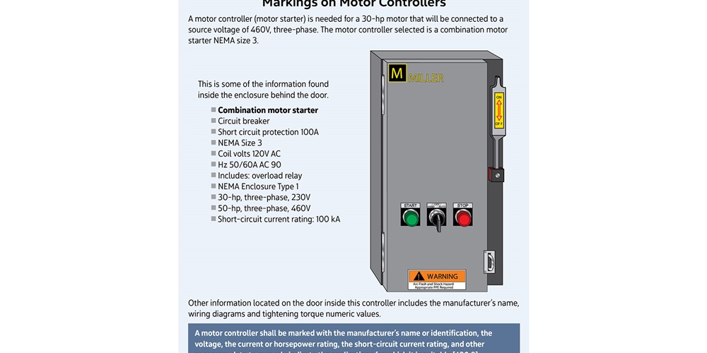
Section 430.8 contains specifications for required markings on controllers. For the purpose of Article 430, a controller is any switch or device that is normally used to start and stop a motor by making and breaking the motor circuit current. In the field, motor controllers are usually referred to as “motor starters.” Markings on motor controllers are typically found inside the enclosure. A motor controller shall be marked with the manufacturer’s name or identification, the voltage, the current or horsepower rating, the short-circuit current rating, and other necessary data to properly indicate the applications for which it is suitable.
For example, a motor controller (motor starter) is needed for a 30-horsepower (hp) motor that will be connected to a source voltage of 460V, three-phase. The motor controller selected is a combination motor starter NEMA size 3. The required information is inside the enclosure behind the door. The label inside the controller shows the manufacturer’s name, voltage, current, horsepower rating, and short-circuit current rating. Most motor controllers will show different horsepower ratings at different voltages. This motor controller shows the maximum horsepower rating is 30 when the motor is connected to a source voltage of 230V, three-phase, and a maximum of 50 hp when the motor is connected to a source voltage of 460V, three-phase. Some of the other information marked on this controller includes the ampere rating of the circuit breaker inside this controller, the operating voltage of the coil, wiring diagrams, and tightening torque numeric values (see Figure 1).
There are four exceptions where the short-circuit current rating is not required to be marked on a motor controller. The first pertains to certain small motors where the branch-circuit disconnecting means can serve as the motor controller and certain small portable motors where the attachment plug and receptacle or cord connector can serve as the motor controller. The second exception states the short-circuit rating is not required to be marked on the controller when the short-circuit current rating of the controller is marked elsewhere on the assembly. The third exception states the short-circuit rating is not required to be marked on the controller when the assembly into which it is installed has a marked short-circuit current rating. Exception No. 4 under 430.8 states short-circuit ratings are not required for controllers rated less than 2 hp at 300V or less and listed exclusively for general-purpose branch circuits.
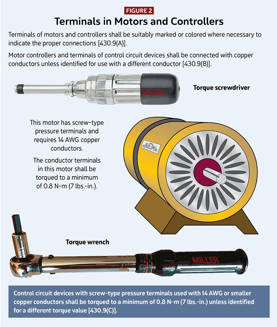
Section 430.9 pertains to terminals in motors and controllers. It is divided into three subsections: Markings, Conductors and Torque Requirements. Some of this section contains requirements for the manufacturer, and some contains requirements for the installer. Terminals of motors and controllers shall be suitably marked or colored where necessary to indicate the proper connections [430.9(A)]. The next subsection states to use copper conductors on motor controllers and terminals of control-circuit devices unless the equipment is identified for use with a different conductor. The third subsection is a requirement for the installer. Control-circuit devices with screw-type pressure terminals used with 14 AWG or smaller copper conductors shall be torqued to a minimum of 0.8 N-m (7 lb-in.) unless identified for a different torque value. While this torque requirement is not new, there is a new torque requirement in Article 110. Where a tightening torque is indicated as a numeric value on equipment or in installation instructions provided by the manufacturer, a calibrated torque tool shall be used to achieve the indicated torque value, unless the equipment manufacturer has provided installation instructions for an alternative method of achieving the required torque [110.14(D)] (see Figure 2).
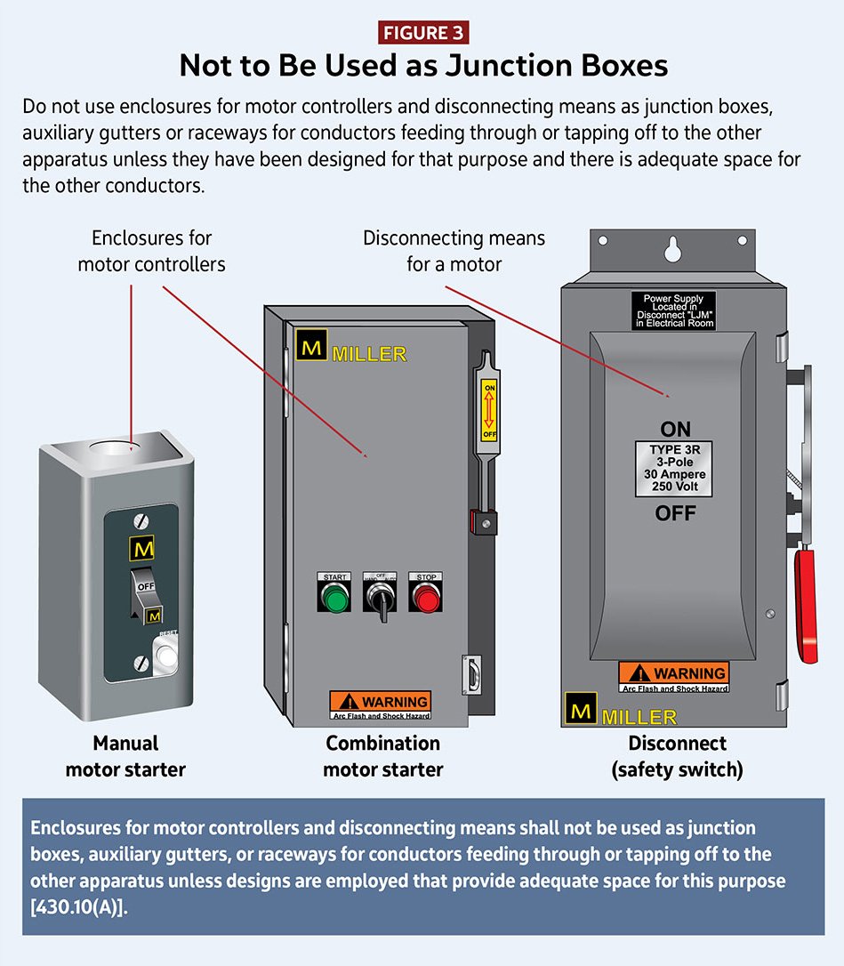
Section 430.10 pertains to wiring space in enclosures for motor controllers and disconnecting means. This section is divided into two subsections: General and Wire-Bending Space in Enclosures. Section 430.10(A) says not to use enclosures for motor controllers and disconnecting means as junction boxes, auxiliary gutters, or raceways for conductors feeding through or tapping off to the other apparatus. It also says enclosures for motor controllers and disconnecting means can be used as junction boxes, auxiliary gutters, or raceways if they have been designed for that purpose and there is adequate space for the other conductors that would be feeding through or tapping off to the other apparatus (see Figure 3).
There shall be sufficient room within enclosures for motor controllers so the conductors are not damaged when they are installed. Minimum wire-bending space within the enclosures for motor controllers shall be in accordance with Table 430.10(B). The minimum space is measured in a straight line from the end of the lug or wire connector (in the direction the wire leaves the terminal) to the wall or barrier. Table 430.10(B) shows wire-bending space for one and two wires per terminal. Conductor sizes range from small conductors up to 900 kcmil. Although there is a row for 10 AWG and smaller conductors, the minimum wire-bending space is not specified.
As stated in the second paragraph in 430.10(B), where alternate wire termination means are substituted for that supplied by the manufacturer of the controller, they shall be of a type identified by the manufacturer for use with the controller and shall not reduce the minimum wire-bending space. Minimum wire bending space also is required for motor controllers that are installed in industrial control panels. Article 409 covers industrial control panels intended for general use and operating at 1,000V or less. As stated in 409.104(B), wire bending space within industrial control panels for field wiring terminals shall be in accordance with the requirements in 430.10(B).
Motors shall be protected against liquids. As stated in 430.11, suitable guards or enclosures shall be provided to protect exposed current-carrying parts of motors and the insulation of motor leads where installed directly under equipment, or in other locations where dripping or spraying oil, water, or other liquid is capable of occurring, unless the motor is designed for the existing conditions. Where a motor is designed to be installed outdoors, guards or enclosures are not required.
Requirements for motor terminal housings are in 430.12. This section is divided into five subsections: Material; Dimensions and Space—Wire-to-Wire Connections; Dimensions and Space—Fixed Terminal Connections; Large Wire or Factory Connections; and Equipment Grounding Connections. In accordance with 430.12(E), there shall be a means to attach an equipment grounding conductor and the means for the connection can be located either inside or outside the motor terminal housing. The means for attaching the equipment grounding conductor shall be provided at motor terminal housings for wire-to-wire connections or fixed terminal connections and shall be in accordance with Section 250.8, which provides a list of permitted methods for connecting equipment grounding conductors, grounding electrode conductors, and bonding jumpers.
Next month’s column continues the discussion of requirements for motors, motor circuits, and controllers.
<< Read Part IV | Read Part VI >>
About The Author
Charles R. Miller, owner of Lighthouse Educational Services, teaches custom-tailored seminars on the National Electrical Code and NFPA 70E. He is the author of “Illustrated Guide to the National Electrical Code” and “Electrician's Exam Prep Manual.” He can be reached at 615.333.3336 and [email protected]. Connect with him on LinkedIn.


