In July, I discussed elevator emergency communication interfaces. This article will talk about elevator emergency operation interfaces.
Emergency operation interfaces
Emergency operation of the elevator involves the connection between the elevator and the fire alarm system. The ASME A17.1 code requires all new elevators to be provided with Phase I emergency recall operation. Phase I is the operation of an elevator where it is automatically or manually recalled to the recall level and removed from normal service. The automatic operation of Phase I is provided by the fire alarm system, and it requires close coordination between the fire alarm system provider, installing contractor and elevator contractor.
The intersecting code requirements of elevators can make it difficult to achieve the correct connection between these separate systems. However, here are six steps that may be helpful:
1. Determine the elevator type and specifics. A designer and installer must know if a hydraulic or traction elevator will be installed because it will determine what hazards exist and thus what emergency interface functions must be provided. The location of the elevator hoistway and the elevator control equipment must be documented and reviewed against the applicable code requirements.
2. Locate smoke detection for elevator lobbies. To activate Phase I elevator recall operation, smoke detection must be placed in each elevator lobby, whether the lobby has one elevator or a bank of them. Smoke detection must be placed on the ceiling within 21 feet of the centerline of each elevator door serving that lobby. If that cannot be met using a single detector location, multiple detectors will be required. Verify any elevator lobbies that may not be suitable for smoke detectors, such as unconditioned parking garage lobbies or rooftop or exterior terrace spaces. Ceilings with unique geometry and those over 15 feet in height will need special detector locations per NFPA 72 Chapter 17.
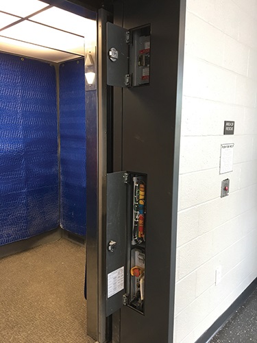
3. Determine control equipment interface requirements. According to the National Elevator Industry Inc., most new elevators serving fewer than 30 landings don’t have a machine room. So it is critical that installers identify the location of the elevator control equipment to know where to install the interface relays between the fire alarm system and the elevator controller. Often, this control equipment may be in an elevator lobby, perhaps even in the elevator door jamb as pictured above. This limits potential installation locations of fire alarm control relays, and it may subject the elevator control equipment or fire alarm equipment to water intrusion from the spray of a fire sprinkler.
4. Determine hoistway requirements. Elevator hoistways are constructed with fire-rated construction. Use NFPA 13 to determine if fire sprinklers will be installed in a hoistway. If fire sprinklers are installed in the top, bottom or both, then smoke detection must be provided for elevator recall and heat detection within 24 inches of each fire sprinkler must be provided for elevator power shutdown activation. If a fire alarm device is activated in an elevator control space or hoistway, then a fire alarm relay must be provided to activate a warning signal to the elevator controller, which will flash the elevator fire hat light within the elevator car.
5. Determine elevator power shutdown requirements. As noted in steps 3 and 4, if fire sprinklers are installed at locations where they can affect the elevator controller or hoistway equipment, elevator main line power shutdown must be provided. This usually requires an EC to install a shunt trip breaker, which is activated through a fire alarm control relay located in proximity to the breaker for each elevator or bank of elevators sharing a hoistway or control space. The fire alarm system must also monitor that power is available to that shunt trip breaker. If that power is lost, a supervisory signal is generated by the monitoring device.
6. Document emergency elevator interfaces. Each elevator can have up to five interfaces and numerous detection types and locations. Although not required by code, it is recommended that a fire alarm designer document each elevator with critical information so the installer knows what is being installed and where. Designers can create a simple fire alarm elevator matrix that details the elevator type, location, landings served and other related information. This can serve as a helpful tool for inspectors and can significantly ease the approval of the elevator installation.
Complying with the various elevator codes can prove challenging for designers and installers. Clear communication between trades becomes critical in laying out and installing code-compliant wire, cable and raceway systems to provide the necessary interfaces between elevators and fire alarm systems.
Header image: MRL elevator with elevator control equipment located within an elevator lobby door jamb / Larry Rietz