
The 1937 classic American song written by the Gershwin brothers, “Let’s Call the Whole Thing Off,” debates two ways to say the same thing. In the power quality realm, we have had a number of different words for the same phenomena, such as surge and transient.
Two other words, unbalance and imbalance, represent the condition in polyphase circuits where the voltage or current of each phase are not equal in magnitude or phase angle relationship to each other. There have also been two different ways to calculate such. The standards organizations have primarily settled on imbalance as being the proper term, as it is a noun meaning lack of proportion or symmetry, whereas unbalance is a verb referring to making something have a lack of balance.
Past articles have discussed the math beyond these two calculations and the advantages and disadvantages. We will leave that behind, and focus here on why it is important in better power quality.
The question of imbalance came up the other day while someone was trying to find the cause of a 15A AFCI breaker tripping, indicating an arcing fault condition in a residence with a typical split-phase voltage configuration. To try to find out more information, the person was going to hook up a monitoring system and was looking for an easy and safe way to connect the voltage leads.
Question of imbalance
The breaker panel had a blank slot opposite the column of the breaker in question, but one row below. By interchanging the breaker with the one opposite, the blank slot would expose the busbar tab to clip onto. But that would change which voltage phase was powering the questionable circuit. This raised the question, would it create an unbalance (imbalance)? That, of course, would require a different type of measurement to identify the existing imbalance conditions for the voltages and currents. We ignored that issue and proceeded on the hunt for the AFCI operation. There was some concern that it could change something if there was an interaction between the tripping circuit and others on that phase. But we also ignored that.
Getting back to imbalance, one of the easiest ways to understand it is through the use of phasor diagrams, such as voltage phasor diagrams for a three-phase wye circuit, as shown in the example above. The phasors show the magnitude by the length of the phasor from the center and the phase relationship between each of the three phases by the angle between them.
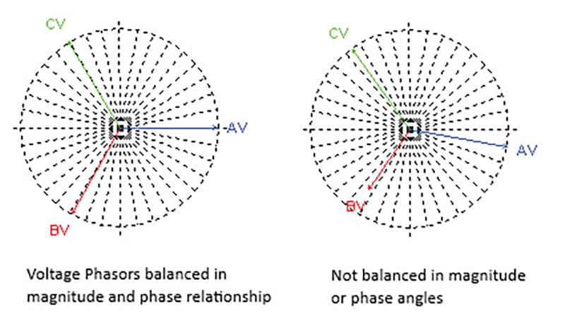
In the right-hand diagram, phase B voltage is shorter in length, or 80% of magnitude of Va and Vc. Phase A voltage is also 10 degrees off from where it is in the left-hand diagram. If we assume a counterclockwise rotation of the phasors, that means it is 10 degrees lagging from before. Phase C voltage is 5 degrees lagging, and Phase B voltage about 2 degrees lagging. This makes the original 120 degrees between phases no longer the case. For example, the A–B phase angle is 117 degrees. This also creates an imbalance in the line-to-line voltages.
Power factor enters the chat
How does this happen, since a properly manufactured three-phase electromagnetic generator starts out all matching in magnitude and phase relationship? Once again, we turn to Ohm’s and Kirchhoff’s laws. The effects from inductive and capacitive components in the circuits can change the voltage-to-current phase angles. By convention, we say that inductive loads cause lagging current and capacitive loads, resulting in leading phase angles. This was the traditional measure of power factor (PF), where it was the angle between the voltage and current. With the increase in harmonic currents (and resulting harmonic voltages), this method also became an inaccurate representation of power factor. Watts/volt-amperes is the more accurate representation of PF.
A decrease in PF means less work is being done by the supplied power and more losses in the wiring between the generator and the load. Remembering the rules we apply for voltage sags, more losses mean reduced voltages at the loads. Reduced voltages with constant power loads result in an increase in currents, which results in the voltage at the load going even lower. This brings the voltage closer to the point where the equipment can misoperate, just like with voltage sags.
Voltage imbalance conditions also cause additional problems with electric motors and transformers. NEMA MG-1 has specified that just a 2% voltage “unbalance” requires a 5% derating of the motors, as overheating, torque reduction and premature motor failure can occur from the resulting high current imbalance. Too high of a current imbalance can result in overcurrent tripping of a breaker.
Though we have kept ignoring the AFCI breaker trips that was the inspiration for the imbalance discussion, hopefully that mystery will be solved by next month’s article.
richard p. bingham
About The Author

BINGHAM, a contributing editor for power quality, can be reached at 908.499.5321.