One possible explanation to last month’s mystery as to why the lights in one bedroom became brighter when the other room’s lights got dimmer was a voltage unbalance. (“Unbalance” is the commonly used term, although most international and IEEE standards use “imbalance.”)
If the two rooms were on different phases of the split-phase circuits that fed the residence, then the neutral conductor (or grounded conductor in NEC speak) has a part in establishing the two phases’ line-to-neutral (L-N) voltage. The residence is fed with the two-phase conductors, and the neutral point is established by connecting the neutral conductor to the ground of the circuit, so its seems logical that this point should be right in the middle. Measuring from L-N on each circuit should read 120V rms when the L-L voltage is 240V rms, though the waveforms are 180 degrees out of phase from each other.
Many contractors have experienced what happens when the neutral conductor is open-circuited. Based on the loads’ impedance on each phase, the two voltages can drift apart significantly, even to destructive levels. If one phase goes to 145V rms while another becomes 95V rms, equipment powered on the high side will likely be damaged by the sustained overvoltage condition. Many surge protectors are designed to only absorb such levels for a relatively short duration, so even they offer little protection. If one had an incandescent bulb on each circuit, the effect would be one going supernova bright while the other went partial-eclipse dim. This wasn’t the case last month, but it was a possibility.
More often, voltage unbalance is an issue with three-phase circuits. Voltage unbalance can increase the heating of three-phase devices such as motors, transformers, drives and rectifier circuits, which means their operating levels need to be derated.
NEMA-MG1 has a curve indicating that a medium-size electric motor should be operated at no more than 95% of the rating for a 2% unbalance. Data from benchmark surveys around the world have shown most distribution systems have voltage unbalances less than 3%, with a 2% limit used in many standards.
IEEE has formed IEEE P2844, a new working group, where the scope of the recommended practice “includes recommended voltage imbalance limits, the determination of the level of voltage imbalance, and the expected voltage imbalance following the connection of new unbalanced loads. This recommended practice also includes information on the impact of unbalanced supply voltage on common end-user and supplier equipment.”
The NEMA and ANSI method for calculating a single number to represent the three-phase unbalance is much simpler than the international standards’ methods. First, you determine the average of the three voltage measures. Then, determine which phase voltage has the largest deviation from the average by subtracting each from the average. Divide the maximum deviation by the average and turn it into a percent by multiplying by 100, which gives a value that works in most situations. The international standards use a method derived from the negative sequence components divided by the positive sequence components, and it is more accurate than the NEMA method. Unless your instrument calculates this parameter, the mathematics required are not familiar to most in the field.
Many sources of voltage unbalance can be attributed to the voltage distribution system itself, where the remediation is normally outside of an EC’s domain. In the facility, voltage unbalance is often caused by current unbalance, which has two components: the magnitude and the phase angle between the three phases, which is 120 degrees in ideal conditions. Having significantly different current magnitudes on the three phases isn’t uncommon in a facility.
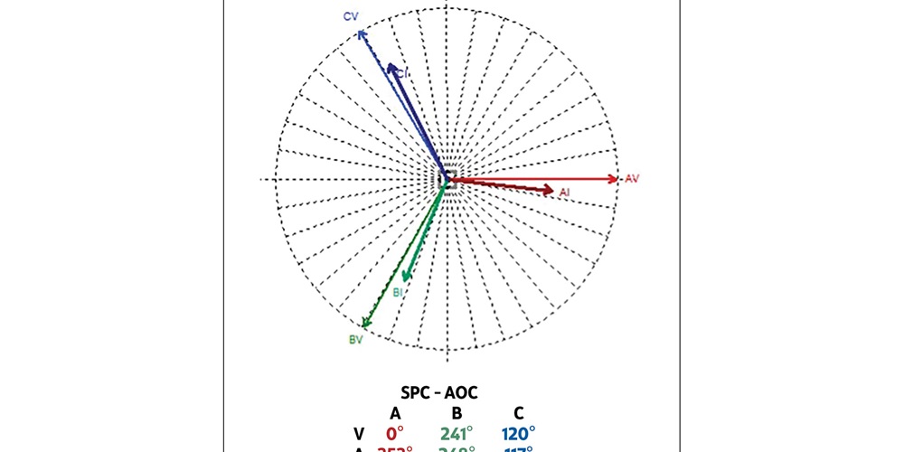
While the initial design should have considered expected loading on each phase, most facilities’ electrical infrastructure evolves over time. Equipment is changed, which affects the loading, or new single-phase equipment can be added that increases the unbalance. Just like all other PQ phenomena, Ohm’s and Kirchhoff’s laws apply. More current on one phase will cause a larger voltage drop across the source impedance, leaving less voltage on the one phase versus the others. The load types can also cause a change in the phase-angle relationship between the voltage and current. The figure below shows an example where the current in Phase B is leading the voltage, whereas the other two currents are lagging, which is more typical. While it isn’t much, it did cause the phase angle of Phase B voltage to be 121 degrees from Phase C and 119 degrees from Phase A. This is enough to cause the voltage magnitudes to be unbalanced.
Voltage unbalance is considered a steady-state phenomena, so it can be detected with simple tools such as a digital voltmeter or current probe. Correcting the problem to prevent damage to equipment can be as simple as swapping wires going to which phase in the breaker panel, once the actual current values are known, and done safely with the circuits de-energized.
About The Author

BINGHAM, a contributing editor for power quality, can be reached at 908.499.5321.