Performing an arc flash study can be complex enough, but the latest edition of IEEE 1584—IEEE Guide for Performing Arc-Flash Hazard Calculations has taken it to a whole new level.
A lot has changed since arc flash studies went mainstream in the early 2000s. The continuing evolution of standards such as NFPA 70E—Standard for Electrical Safety in the Workplace and the latest edition of IEEE 1584, coupled with advancements in arc-rated clothing and personal protective equipment (PPE) and changes to electrical design practices, have led to significant improvements in electrical safety.
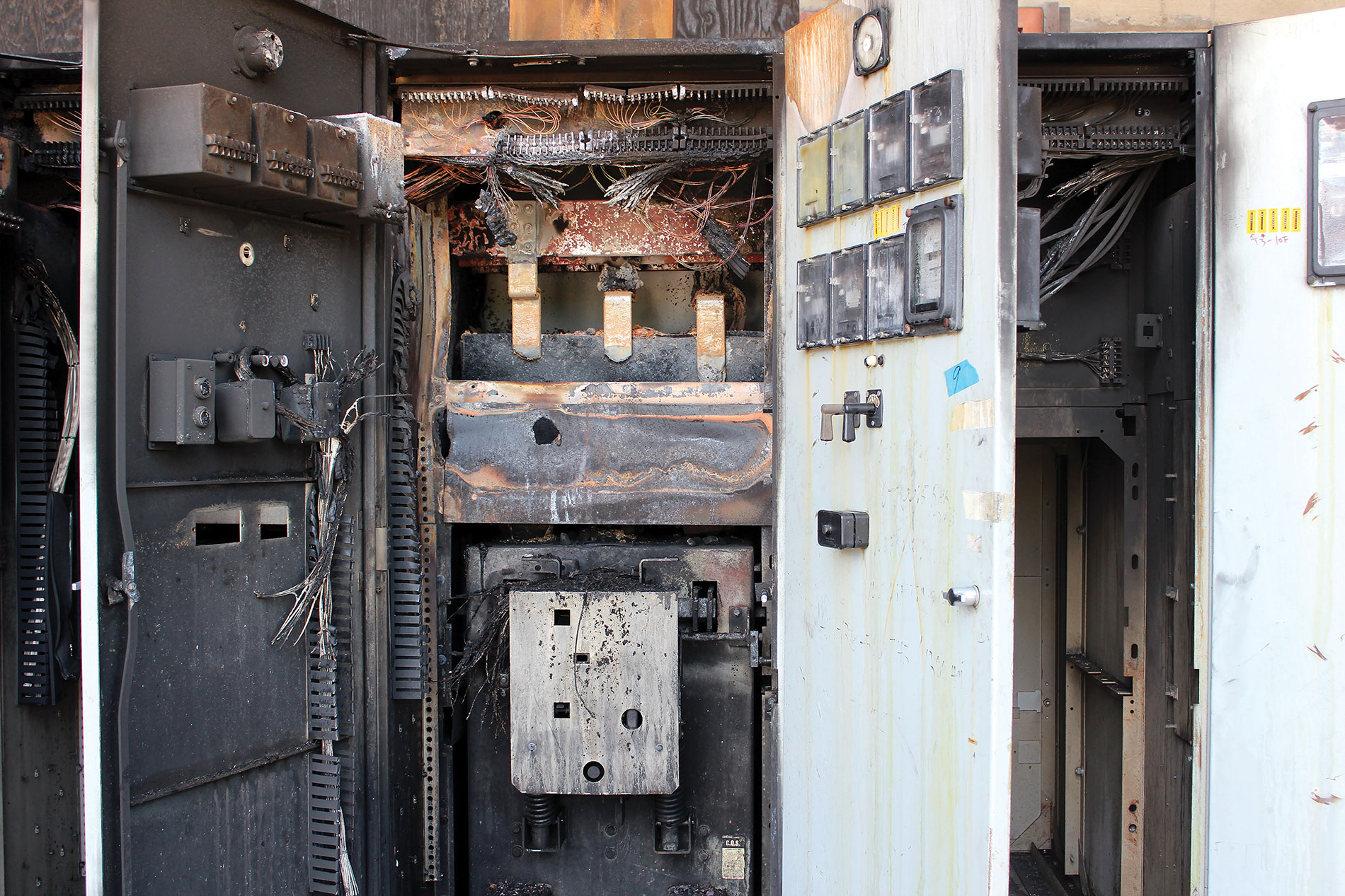
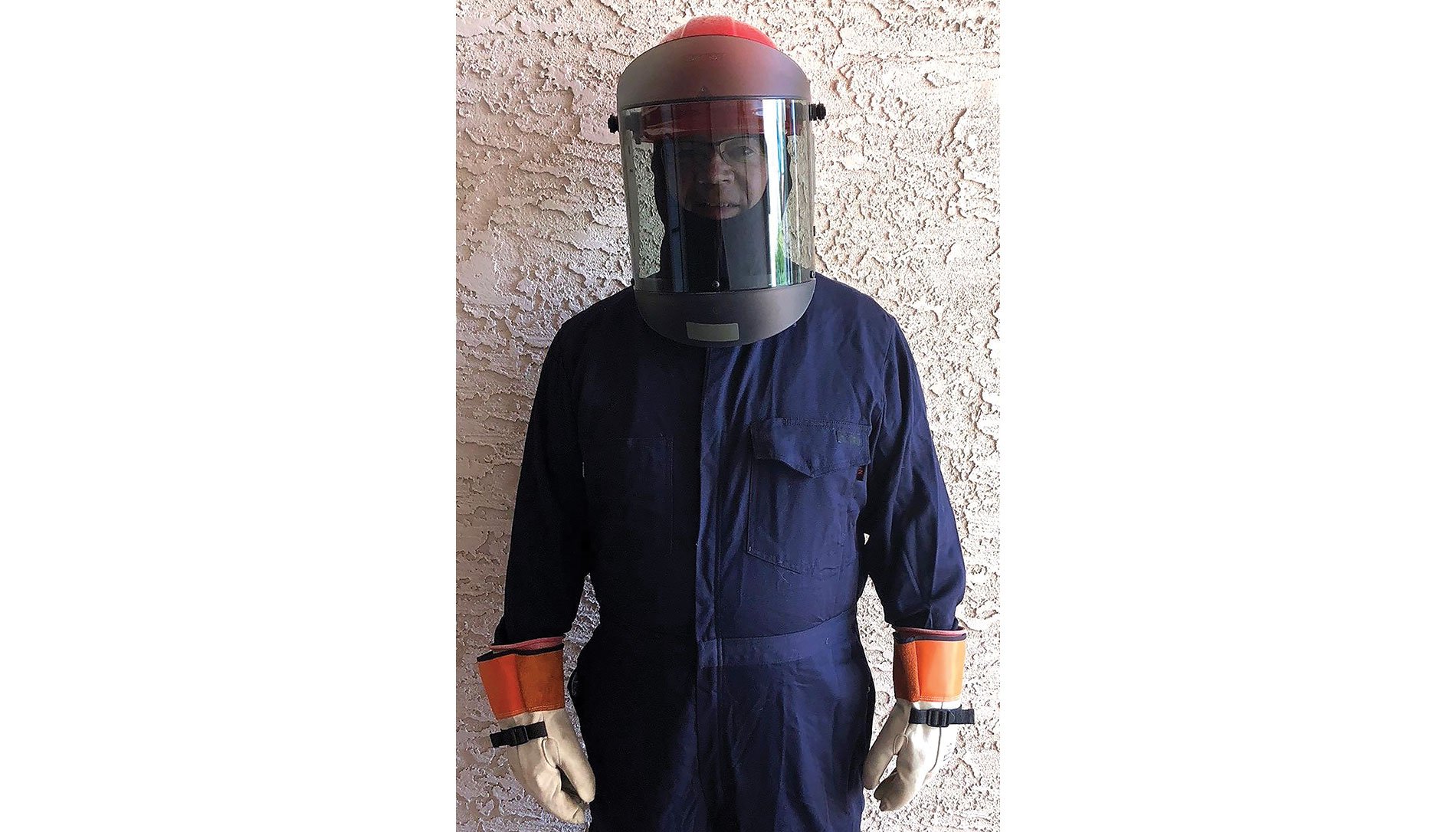
The primary focus of an arc flash study is the calculations of arcing fault current, incident energy and arc flash boundary. The final results of the study are used to select arc-rated PPE and clothing with a sufficient arc rating and establish what is known as an arc flash boundary. This information is also important for arc flash (equipment) labels and energized electrical work permits. The photo above illustrates what can happen when things go wrong.
What code or standard requires the arc flash study? NFPA 70E 130.5, Arc Flash Risk Assessment, requires that arc flash PPE be selected by using either the arc flash PPE category method or by performing an incident-energy analysis.
The PPE category method relies on tables in NFPA 70E that assign PPE categories based on the equipment type and specific parameters. The incident-energy analysis method requires calculating the prospective incident energy that could result from an arc flash. The arc rating of PPE is selected according to this value. NFPA 70E stops short of requiring a specific calculation method for the incident-energy analysis. However, globally most use the IEEE 1584 standard.
Incident energy is defined by NFPA 70E and IEEE 1584 as “the amount of thermal energy impressed on a surface, a certain distance from the source generated during an electric arc event.” In other words, it defines the severity of an arc flash and is quantified as calories/centimeter2 (cal/cm2).
Although the IEEE 1584 calculations are known as an incident-energy analysis, this is just one component of what most consider an arc flash study. Additional components may include defining risk-control methods for the arc flash, arc flash (equipment) labels and a shock risk assessment.
Results from a short-circuit and coordination study are also necessary for determining the available fault current at the equipment location and the arc duration based on how long it takes a specific upstream protective device to operate and clear the fault during an arc flash. This information can be obtained from previous studies as long as the results have been verified as correct. If there are no existing studies or the accuracy cannot be verified, new or revised studies may need to be performed. Relevant standards such as IEEE standards should be used for these additional studies.
Legal
Before we go any further, two items need to be addressed. First, the person performing the study should be qualified to do so. In this age of “There’s an app for that,” errors can occur with potentially catastrophic results. IEEE 1584 defines a qualified person as “a person who performs arc-flash hazard calculations by using skills and knowledge related to the construction and operation of the electrical equipment and installation and has experience in power system studies and arc-flash hazard analysis.”
Note the IEEE 1584 definition of qualified person addresses the person performing the study is different than the NFPA definition of a qualified worker, which addresses the electrical worker.
Second, although I am very involved with many of the standards used for an arc flash study, the views here are mine and may or may not reflect those of any particular standards organization.
Arc flash study—480V panelboard
To illustrate the steps for performing an arc flash study, a 480V three-phase panelboard was selected as an example. A large amount of data is required and will be discussed step by step. The reader is also encouraged to obtain a copy of the 2018 edition of IEEE 1584 for the complete equations and details.
The old saying “You can’t see the forest for the trees” is appropriate for the arc flash study. It simply means don’t become so caught up in the small details that you are unable to step back and see the big picture. Just like in the forest, it is easy to get lost in the details of the study. I suggest you keep one simple concept in mind: the primary goal of an arc flash study is to select arc-rated PPE that is sufficient for the calculated incident energy.
This means that if one assumption results in a calculated incident energy of 4.2 cal/cm2, another is 4.6 cal/cm2 and the third is 5.2 cal/cm2, if PPE is selected with a minimum arc rating of 8 cal/cm2, it is considered sufficient regardless of which of the three calculated incident energy values are used. The effect on the arc flash boundary will be addressed later.
I like to use the analogy of a short-circuit study. When performing one, let’s say a particular panel has a short-circuit interrupting rating of 22 kiloamperes (kA). Using different assumptions in the study could result in a different calculated short-circuit current, such as 12.5, 13.5 and 14.1 kA. But in the end, the 22-kA panel is adequate for all three values. Accuracy is critical, and this statement is not to diminish the importance of using exact data. Just make sure you continue to the see the big picture.
Step one: Data collection
The data requirements for an arc flash study can be broken down into three categories: impedance data for a short circuit study, protective device data to define the arc duration and equipment data used to define the enclosure size, bus gap and electrode configuration. Depending on the age of the system and existing documentation, data collection could potentially be a significant portion of the overall study effort. Often, not all of the data is available and conservative assumptions may be necessary and documented.
The first step in performing an arc flash study is to create a computer model of the power system under study. Commercially available software can simplify the process with their vast libraries by enabling the creation of a one-line diagram and entering the necessary data.
Be careful not to fall victim to what I refer to as “data paralysis.” This is where all of the data is not immediately available and causes the study effort to stall out. One trick when data is not yet available is to substitute very unusual data that sticks out as a space holder. That way a preliminary model can be completed. As an example, if conductor lengths are unknown, temporarily use conductor lengths of 3 feet. This enables developing a functioning model before the study becomes bogged down. Once the final data is obtained, the unusual numbers can be replaced.
Step two: Available fault current
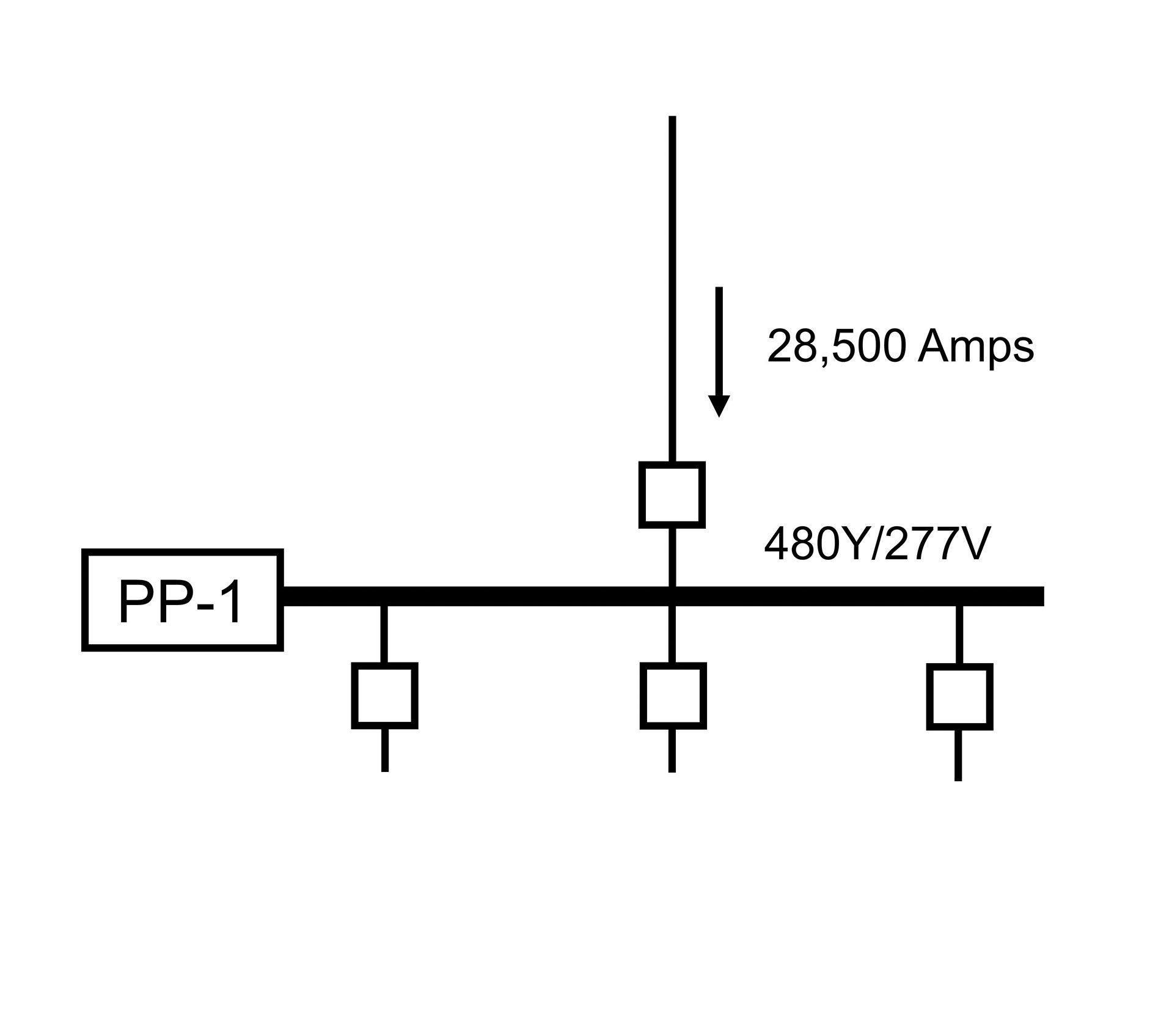
After the model had been created, the first calculation step is to determine the available bolted three-phase fault current at each location. This is one of the main variables used to determine the incident energy. I often refer to the fault current as defining the intensity or explosiveness of the arc flash. A greater current results in a more powerful arc flash. However, it does not always translate into the greatest incident energy, as we will see further on in this article.
The results of a separate fault current study indicate the three-phase bolted fault current is 28,500A at the panel shown in the figure below, which will be the starting point for our example.
Step three: Arcing short-circuit current
A traditional fault current study from step two is used to determine the “bolted” fault current that is normally used to evaluate the interrupting capability of protective devices. The term “bolted” means the short is a solid connection with no additional impedance at the fault.
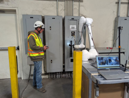
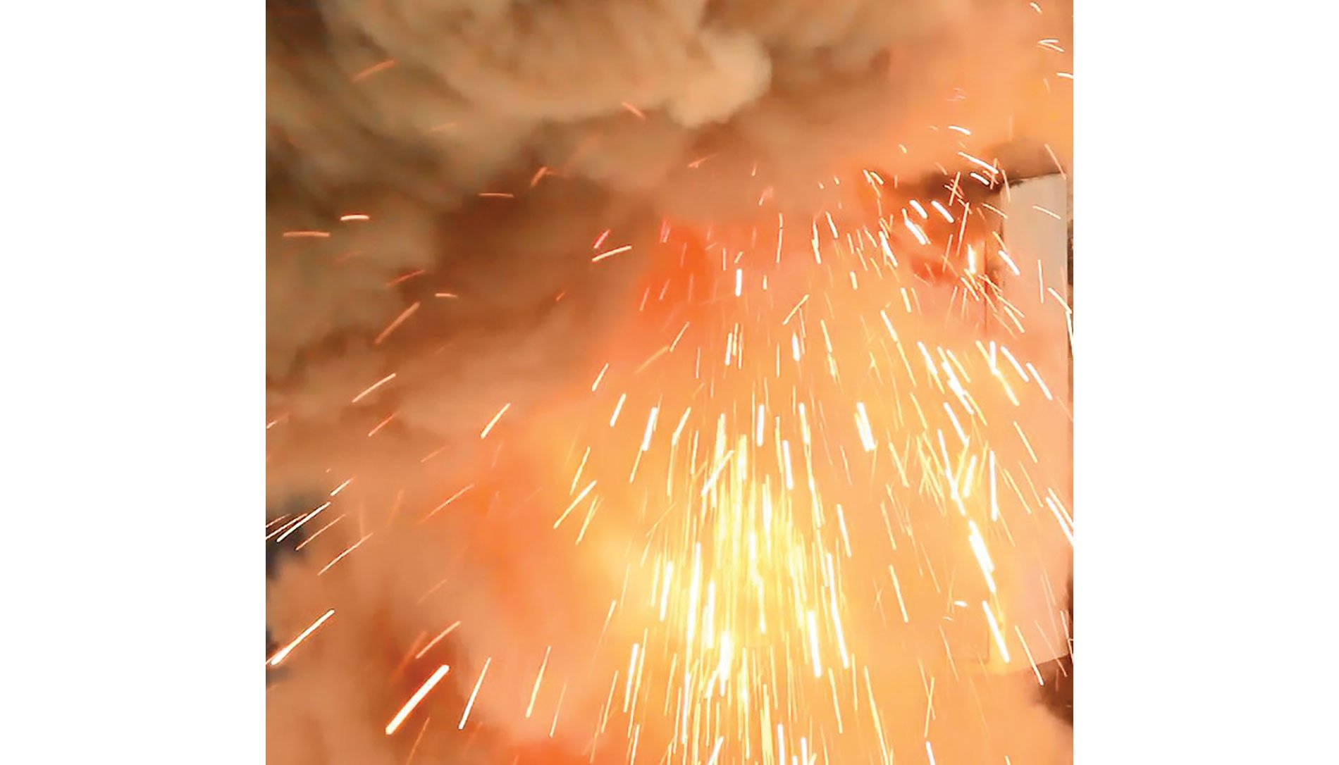
However, during an arc flash, the conductors or conducting object that initiates the fault either melts back or is blown back, creating a gap in the current path. The photo above shows an example of what happened during an arc flash test staged by the author. The fault current flows across the gap, ionizing the air and creating a plasma. Known as an arcing fault current, IEEE 1584 equations require many input variables for this calculation, such as bolted three-phase short-circuit current, bus gap, electrode configuration and voltage.
A table of “typical” bus gaps is provided in IEEE 1584. At low voltage, the typical gaps are 25 mm for distribution equipment, such as panelboards, switchboards and motor control centers, to 32 mm for low-voltage switchgear. Since this arc flash study example is a panelboard, 25 mm was selected. The user can apply their own defined bus gaps. However, it must be noted that the gaps can vary within this same piece of equipment and with different equipment.
The results will be analyzed using different electrode configurations, arc duration and enclosure sizes in a later article.
Read part 2 >>
About The Author

PHILLIPS, P.E., is founder of brainfiller.com and provides training globally. He is Vice-Chair of IEEE 1584 Arc Flash Working Group, International Chair of IEC TC78 Live Working Standards and Technical Committee Member of NFPA 70E. He can be reached at [email protected].