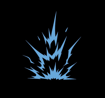
An arc flash occurs when short-circuit current jumps across an air gap between energized conductors. The event is normally the result of initial (and inadvertent) contact between energized conductors that creates the short circuit. During the event, the conductors or a conducting object may either melt back or be blown back, producing an air gap. When current flows across the gap, it ionizes the air, resulting in a conducting plasma and thermal cloud.
IEEE 1584—IEEE Guide for Performing Arc-Flash Hazard Calculations refers to this as the arcing fault current, defined as “a fault current flowing through an electrical arc plasma.” To calculate the arcing fault current, IEEE 1584 equations require many input variables such as bolted three-phase short-circuit current, bus gap distance, electrode configuration and voltage.
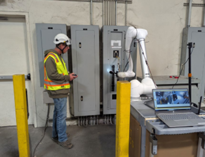
Measuring the actual gap distance is usually impractical, since it would require placing each piece of equipment that may be energized in an electrically safe work condition and evaluating it. In addition, a piece of equipment may have several different gap distances, depending on where the arc flash occurs.
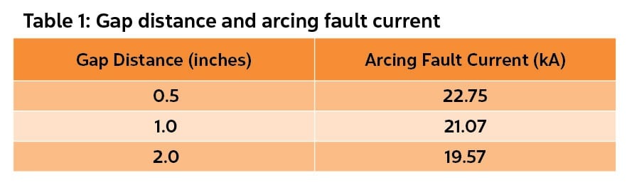
IEEE 1584 provides a range of valid gap distances from 0.25–3 inches for voltages from 208V–600V. The standard also lists typical gap distances for equipment classes such as 1 inch (25 mm) for low-voltage motor control centers and panelboards and 1.25 inches (32 mm) for low-voltage switchgear. These values are often used for arc flash studies in the absence of measurements. The example problem from Part 1 of this series (“How to Perform an Arc Flash Study” in the September 2021 issue of ELECTRICAL CONTRACTOR) is based on a bolted fault current of 28,500A at 480V.
Table 1 lists the calculated arcing fault current using different gap distances. It illustrates how the arcing current increases as the gap distance decreases and vice versa.
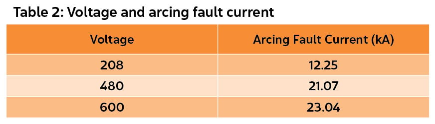
The magnitude of arcing fault current is also voltage-dependent. As the voltage decreases, the arcing current also decreases, as shown in Table 2.
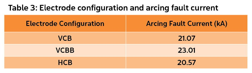
The introduction of different electrode configurations was one of the most significant additions to the second edition of IEEE 1584. Three of the configurations are used for equipment inside an enclosure. These include VCB (vertical conductors inside a metal box), VCBB (vertical conductors terminated in an insulating barrier inside a metal box) and HCB (horizontal conductors inside a metal box). See “Questions and Answers” from the May 2019 issue and “Let’s Consider Incident Energy” from the July 2019 issue of ELECTRICAL CONTRACTOR for details on electrode configurations.
IEEE 1584 provides some guidance regarding the selection of electrode configurations. However, it is up to the qualified person performing the study to make the final determination. It is possible to have several different electrode configurations in a single piece of equipment, depending on where the arc flash occurs. Also, just because equipment has a horizontal does not automatically mean the electrode configuration is HCB. HCB is for horizontal bus/electrodes aimed at the worker. Similarly, if the equipment bus is in a vertical orientation, that does not necessarily translate into VCB or VCBB. What if there are stabs pointed toward the worker from the vertical bus? That may result in an HCB configuration.
The electrode configuration affects the arc trajectory and the arc impedance. VCBB results in the lowest arc impedance due to the concentration of plasma at the insulating barrier and yields a greater arcing fault current. Each electrode configuration can result in a different arcing current, as shown in Table 3, as well as different incident energy and arc flash boundary.
The calculations for our panelboard example defined in part 1 would likely use VCB and VCBB. Why? When conductors terminate into a main protective device such as the top of a panel, it may behave like a VCBB configuration at that location.
However, if an arc flash occurs on a branch device, this may act more like VCB. Why analyze both? Because either one could result in the worst-case incident energy. If the arc duration is the same for each case, VCBB will result in the greater incident energy. However, VCB can result in a lower arcing current, which could cause an upstream protective device to take longer to operate. The longer arc duration could result in a greater incident energy for VCB.
<< Read part 1 | Read part 3 >>
About The Author

PHILLIPS, P.E., is founder of brainfiller.com and provides training globally. He is Vice-Chair of IEEE 1584 Arc Flash Working Group, International Chair of IEC TC78 Live Working Standards and Technical Committee Member of NFPA 70E. He can be reached at [email protected].