Installing grounding electrode conductors (GECs) to Code
Welcome back to this series about understanding Article 250 of the National Electrical Code. Grounding and bonding are critical parts of how we safely install electrical systems.
Previously, we focused on sizing the grounding electrode conductor (GEC), which is a critical component of the grounding system that connects the system to earth. Remember, one purpose of grounding an electrical system is to limit the voltages imposed on it. A properly sized GEC ensures this happens.
While still focusing on the GEC, let’s examine the NEC requirements on installing the GEC for protection from damage and retaining the integrity of connections. First, how do we protect the GEC from damage? Section 250.64 provides requirements for GEC installation that can help.
Note: Proper GEC routing and protection not only ensure code compliance but also safeguards against long-term system degradation and safety risks.
Corrosion protection and conductor materials
Be aware that corrosion causes major problems on a GEC. Corrosion can compromise conductor continuity and increase resistance, weakening the system’s ability to stabilize voltage and safely dissipate fault energy. The GEC can be copper, aluminum or copper-clad aluminum (CCA), and corrosion is a concern for aluminum and CCA conductors.
If aluminum or CCA-type GECs are bare or covered by something other than extruded polymeric material, direct contact with concrete is not allowed due to corrosion. And this is not the only concern. We also aren’t allowed to terminate the conductors within 18 inches of the earth unless inside an enclosure listed and identified for the location.
In this case, an aluminum or CCA conductor can be terminated within 18 inches of the bottom of the enclosure. Other corrosive conditions, such as those found near pools and fountains, industrial manufacturing plants and salt water must not use aluminum or CCA grounding electrode conductors either. Notice that these requirements don’t apply to copper GECs, as there is not the same threat of corrosion.
What about physical damage to the GEC? It depends on whether the GEC is 6 AWG or larger. If so, and the GEC is not exposed to physical damage, it can be run along the surface without any additional protection. However, if it’s smaller than 6 AWG or in an area where physical damage is likely, then the GEC must be run in some sort of conduit, tubing or cable armor.
Metal raceways must be bonded to the conductor at both ends and electrically continuous from end to end. There are several listed fittings available that help to bond this raceway. This is to prevent what is commonly referred to as a “choke” effect on the GEC.
Continuous from end to end
Section 250.64 also requires the GEC to be continuous from end to end. If a splice or joint is necessary, there are some conditions that must be met. Wire-type GECs that have to be spliced must use either a compression-type irreversible connector listed for grounding and bonding or be joined using an exothermic welding. For GECs that consist of busbar, it is permissible to connect multiple sections together.
Similarly, because metal water pipes and building steel are permitted to be a GEC to connect to the actual electrode, the typical connections of these systems are permitted. Examples include bolted, welded, riveted, brazed, soldered and threaded connections.
However, if a device or fitting is installed in the water line, such as a meter, it is required to bond around this device.
There are also requirements for GECs in systems with multiple disconnecting means in separate enclosures. One option includes running a common GEC and several taps that are connected either to a busbar by exothermic welding, or by listed grounding and bonding equipment. An alternative is installing individual GECs on each electrode or in an enclosure on the supply-side of the disconnect, tying the individual GECs together to supply-side bonding jumpers or the grounded conductor. We can also make this connection to the equipment grounding conductor for feeders. We will look at a service with multiple disconnects in the future.
How do we get the GEC to the electrode? We could install individual GECs to each electrode present. However, we can connect electrodes with bonding jumpers and install one GEC to a convenient location on the system. The GEC used to connect to the system must be sized per the largest GEC required for the electrodes present. A busbar system is also permitted to connect the individual bonding jumpers with a single GEC from the disconnect to the busbar. Since not all electrodes require the same size GEC, this is popular when there are multiple electrodes.
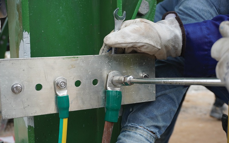
Making secure connections to grounding electrodes
The last concern is the final connection to the electrode. In general, this connection is required to be accessible, with exceptions for buried or encased connections and irreversible compression fittings or exothermic welding connections. The connection to the electrode must ensure an effective grounding path, meaning that the grounding path must be electrically continuous. Jumpers around any nonconductive paths such as meters, gasketed flanges, or prepainted building steel connections are required. This helps maintain the grounding path when items are serviced.
There are also requirements for underground metal water pipe and concrete-encased electrode connections. Because these electrodes are not accessible during the electrical installation process, we are permitted to extend the GEC connection to the actual electrode.
The GEC must connect to interior metal water piping within the first 5 feet of pipe in the building. Don’t forget, it must be electrically continuous around nonconductive joints, valves and meters.
Rebar-type concrete-encased electrodes are also permitted to be extended beyond the footing for GEC connection, with a few conditions. First, extensions must be continuous with the rebar electrode section or must be connected to the electrode with the typical steel tie wires. The extension is not permitted to be in contact with earth unless corrosion protection is used, and the extension is not permitted to connect other electrodes such as ground rings and rods. Often the extension is stubbed into an exterior wall to make the connection—just remember the accessibility rule.
Finally, building steel is permitted to be used throughout the building as a GEC. This means that if the building has a continuous steel frame, connection can be made close to the service equipment, and the steel can carry the connection to the metal in-ground support structure.
If the frame is bolted down to footings, the hold-down bolts can make the final connection to a concrete-encased electrode, provided the footing contains rebar and meets all qualifications of such an electrode.
Best practices for installing GECs and grounding electrodes
This is a basic explanation of how to install the GEC and connect to various grounding electrodes. Of course, there are always more potential variations.
Install the GEC so that it’s unlikely to be damaged and maintains its integrity and connects to the electrode in a manner that provides an effective grounding path. Following these requirements ensures our electrical systems meet the intent of grounding them in the first place. By properly sizing, installing and bonding GECs, electricians enhance both electrical reliability and personnel safety in every installation.
Until next month, stay safe and always remember to test before you touch!
stock.adobe.com / Tanakorn
About The Author

Vigstol is an electrical safety consultant for E-Hazard, a provider of electrical safety consulting and training services. He is also the co-host of E-Hazard’s electrical safety podcast “Plugged Into Safety.” For more information, check out www.e-hazard.com.