The reigning champ of most common power quality disturbances is the voltage sag, as you may remember from January. I once saw a lineworker’s log book that had a category called “blinks”—if the lights blink, check that box. However, knowing you have a blink is only the first step in the investigation. Identifying the “whodunit” is the next question. Two simple rules can eliminate any finger-pointing and use the data to give an accurate answer.
While artificial intelligence isn’t required to figure this out, you will need a power quality monitor or analyzer that accurately captures the voltage and current waveforms and computes the rms voltage and current for each cycle, preferably on a half-cycle step. That means for one power frequency cycle—16.66 msec at 60 Hz—all of the sampled data points are used to generate the rms value. Then, a half-cycle later (8.33 msec), it is done again.
It is also good to have a few prefault and postfault data cycles along with the cycles during the sag. Any of the PQ monitors certified to comply with IEC 61000-4-30 will do this. Although the waveforms themselves aren’t required, it is nice to see them, as a picture is worth a whole lot of words!
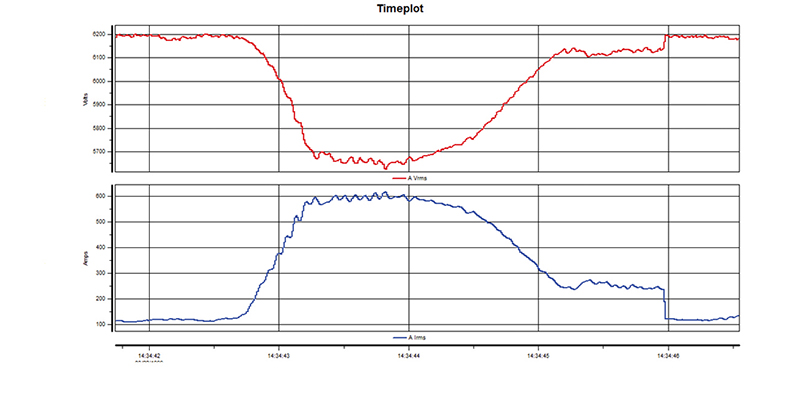
Figure 1: Inrush current causing sag
Remember, directivity of a voltage sag is relative to the point where the measurement is made. If the PQ monitor is connected at the service entrance, the point of common coupling between utility equipment and facility equipment, then an indication of upstream means the source of the sag is the electric utility or the power supplier.
Conversely, downstream means something in the facility caused it. If the PQ monitor is connected to a circuit off a breaker panel, then downstream would indicate that some equipment or wiring issue on that circuit is responsible for generating the voltage sag.
Two basic rules
We use two basic rules for the source versus load determination, one for downstream and one for upstream. Contrary to most people’s impressions, most PQ problems originate while consuming power within the facility, not from the electric source. Hence, it’s simpler to apply the downstream rule first.
Rule No. 1 is that if the voltage decreases when the current increases significantly, its cause is mostly likely downstream from the monitoring point. Perhaps the easiest example is with a large inrush current, as shown in Figure 1. The presag voltage is approximately 6,200 Vrms at 120 Arms. The initial inrush current peaks at 600 Arms, causing the voltage to drop to 5,660V, then decreases to the pre-event levels in 3.2 seconds.
Remembering Kirchhoff’s and Ohm’s laws, this makes sense due to the voltage drop across the source impedance. And no, this is not a typical voltage sag, as a reduction below 90% of nominal is a common threshold limit. But the limits can be set to the point where the equipment may malfunction.
The flipside rule for upstream is a bit more complex due to the variations on how the power supplies in different loads react to a reduction in voltage. The current may increase only slightly, decrease proportionately or drop to zero. The latter is common with the rectified input power converters used in most electronic loads, such as computers and printers, because there is a large capacitor on the output of the AC-DC rectifier that stores up energy until it is depleted.
When the voltage from the source drops below the voltage on the capacitor, the diodes in the rectifier block reverse current flow. If the load is still running, the energy on the capacitor will be reduced and current will begin to flow again. With a linear load, such as a toaster oven, the current reduces in proportion to the voltage reduction. Figure 2 shows an upstream or source side sag.
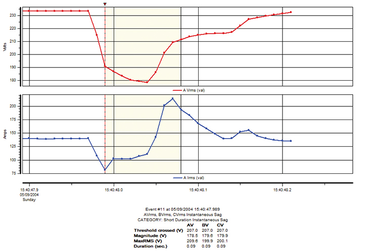
Figure 2: Upstream or source side sag
Some PQ monitors on the market use these rules and others to classify the rms voltage variations as upstream or downstream, as well as the type of transients. However, with just the basic rms plots of voltage and current and a bit of practice while remembering the rules, determining the source isn’t that difficult in most cases.
As for the blinks in the lineworker’s log book, the changeover from incandescent and fluorescent to LED may have decreased the statistics on blinks because of their potential longer ride-through capability with a decently sized capacitor on the rectifier circuit. Sounds like experiments are needed.
Richard p. Bingham
About The Author

BINGHAM, a contributing editor for power quality, can be reached at 908.499.5321.