Do you know what a feeder is, where it starts and ends and how to size the conductors and overcurrent protection? What about surge protection and barriers?
In accordance with Article 100, “feeders” are the conductors between a service disconnect, transformer secondary, generator output or other power production sources such as a solar photovoltaic system disconnect and an energy storage system disconnect, and the final branch-circuit overcurrent protective device (OCPD).
The requirements for feeders within Article 215 are different than those for services contained in Article 230 and branch circuits in Article 210. Therefore, it is important to properly understand the differences between a feeder and a service or branch circuit.
Article 215 contains the general requirements for the installation, conductor sizing, overcurrent protection and surge protection for feeder circuits [215.1].
Conductor sizing
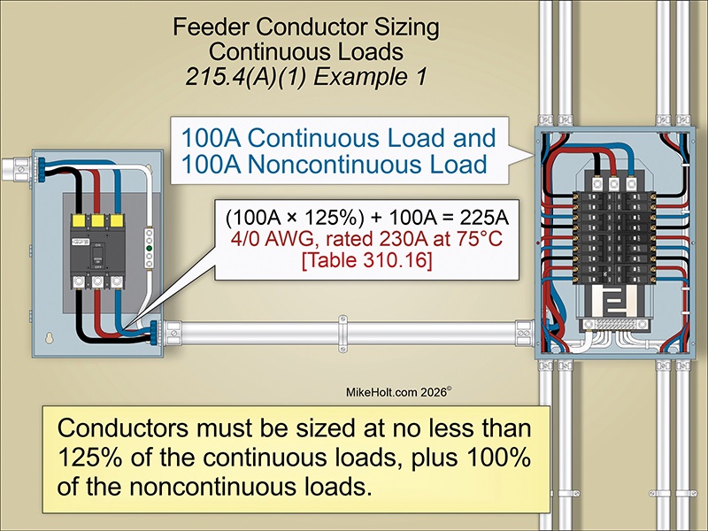
The ampacity of the feeder conductors must be no less than 125% of the continuous loads, plus 100% of the noncontinuous loads.
Let’s go over two examples of this calculation. Example 1 looks at continuous and noncontinuous loads.
Question: What size copper feeder conductors are required for a 100A continuous load and 100A noncontinuous load?
A. 1/0 AWG
B. 2/0 AWG
C. 3/0 AWG
D. 4/0 AWG
Solution: Step 1, determine the minimum conductor ampacity.
- Minimum conductor ampacity = (100A × 125%) + 100A
- Minimum conductor ampacity = 125A + 100A
- Minimum conductor ampacity = 225A
Step 2, determine the conductor size.
4/0 AWG rated 230A, 75°C column of Table 310.16
Answer: D. 4/0 AWG
Next let’s look at example 2, continuous load only.
Question: What size copper feeder conductors are required for a 180A continuous load?
A. 1/0 AWG
B. 2/0 AWG
C. 3/0 AWG
D. 4/0 AWG
Solution: Step 1, determine the minimum conductor ampacity.
- Minimum conductor ampacity = 180A × 125%
- Minimum Conductor Ampacity = 225A
Step 2, Determine the conductor size.
4/0 AWG rated 230A, 75°C column of Table 310.16
Answer: D. 4/0 AWG
Overcurrent protection sizing
Feeder OCPDs must have an ampere rating of no less than 125% of the continuous loads, plus 100% of the noncontinuous loads [215.5].
Let’s consider an example of continuous and noncontinuous loads.
Question: What size feeder OCPD is required for a 100A continuous load and a 100A noncontinuous load?
A. 200A
B. 225A
C. 250A
D. 300A
Solution:
- OCPD = (100A continuous load × 125%) + 100A noncontinuous load
- OCPD = (100A x 125%) + 100A
- OCPD = 125A + 100A
- OCPD = 225A [240.6(A)]
Answer: B. 225A
Conductor identification
The feeder neutral conductor must be identified white or gray in accordance with 200.7 [215.12(A)], and the feeder equipment grounding conductor must be identified green, green with a yellow stripe or bare in accordance with 250.119 [215.12(B)].
Identification of the feeder phase conductors must be as follows:
(1) Feeder phase conductors for premises wiring system with only one nominal voltage system must be identified with other than white, gray or green in accordance with 310.6(A)(3).
(2) Where the premises wiring system has feeders supplied from more than one nominal voltage system, the feeder phase conductors must be identified by phase and nominal voltage system at termination, connection and splice points, as follows:
(a) Feeder phase conductor identification can be by color coding, marking tape, tagging or other means approved by the authority having jurisdiction (AHJ).
(b) Feeder phase conductor identification must be readily available or posted at the panelboard.
Author’s comment
When a premises has more than one nominal voltage system, the phase conductors must be identified by the phase and voltage system. This can be done by permanently posting an identification legend that describes the method used (such as color-coded marking tape or color-coded insulation).
Whichever color scheme is used, it is important that it remains consistent wherever phase conductors are terminated throughout the premises.
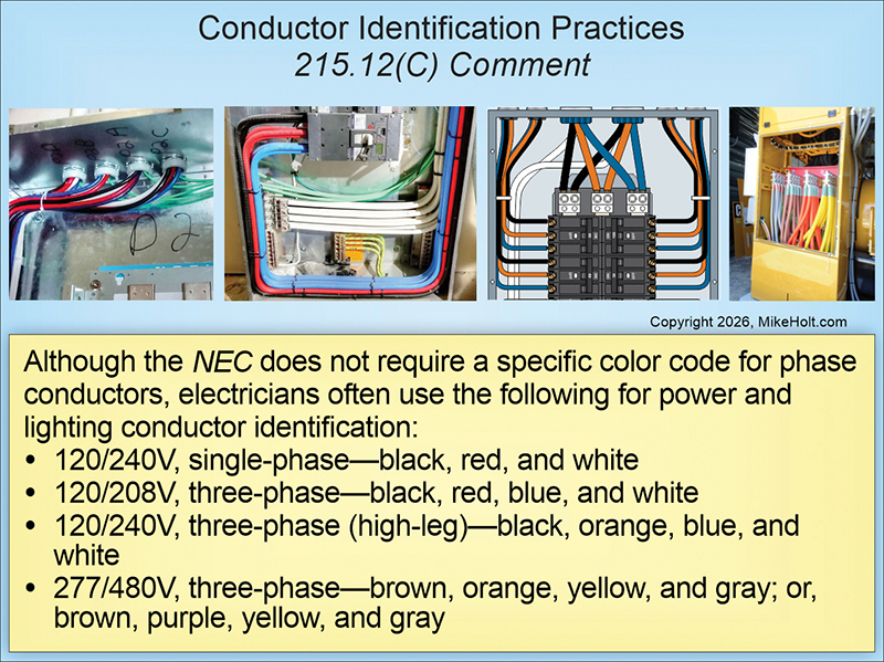
The NEC does not require a specific color code for phase conductors, but electricians often use the following colors:
- 120/240V, single-phase: black, red and white
- 208Y/120V, three-phase: black, red, blue and white
- 240V/120V, three-phase (high-leg): black, orange, blue and white
- 480Y/277V, three-phase: brown, orange, yellow and gray; or brown, purple, yellow and gray
Barriers
During maintenance and servicing, an electrician can be exposed to energized parts on the line side of a feeder tap or transformer secondary conductor termination into an OCPD, even if the disconnect is in the open position.
Barriers must be placed on energized phase terminals of panelboards or switchboards supplied by the following [215.15]:
- A feeder tap conductor; see 240.21(B).
- Transformer secondary conductors; see 240.21(C).
Surge protection
If a feeder supplies any of the following areas, a Type 1 or Type 2 surge protective device (SPD) is required [215.18(A)]:
(1) Dwelling units
(2) Dormitories
(3) Guest rooms and guest suites of hotels, motels and dormitories
(4) Areas of nursing homes and limited-care facilities used exclusively as patient sleeping rooms
(5) Areas for sleeping quarters in fire stations, police stations, rescue stations, ambulance stations, ranger stations and similar locations
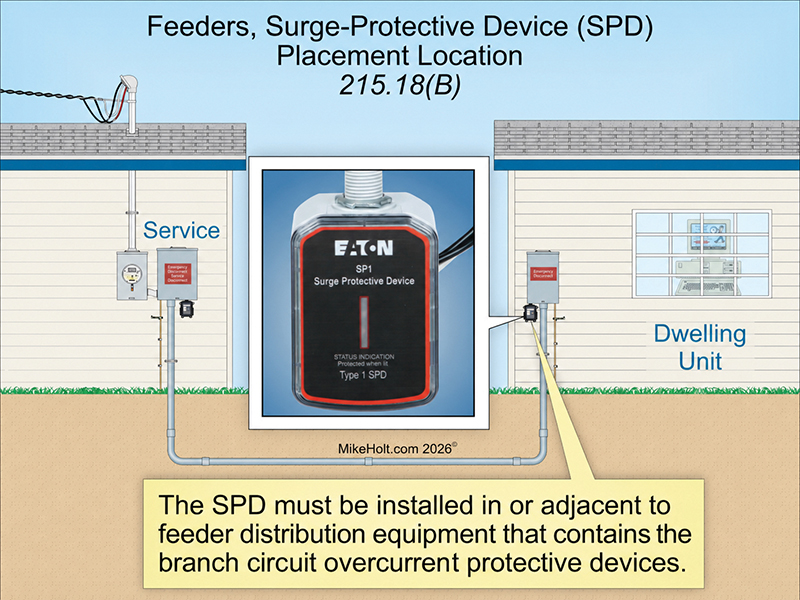
The SPD must be installed in or adjacent to the feeder distribution equipment containing the branch circuit OCPDs [215.18(B)].
Surge protection from surges generated from lightning, the electric utility or utilization equipment is most effective when located closest to the branch circuits [215.18(B) Note].
Surge protection helps protect life safety electronic equipment like AFCIs, GFCIs and smoke alarms.
Where feeder-supplied distribution equipment is replaced in dwelling units, dormitories, guest rooms and guest suites of hotels or motels, and areas of nursing homes and limited-care facilities used exclusively as patient sleeping rooms, an SPD is required [215.18(D)].
SPDs must have a nominal discharge current rating (In) of at least 10 kA [215.18(E)].
Getting feeders right
- Identify the continuous and noncontinuous loads, calculate the feeder load and properly size the conductors and overcurrent protection.
- Make sure the feeder conductors are consistently identified throughout the premises.
- Place barriers on energized phase terminals of panelboards or switchboards in accordance with 215.15.
- If a feeder supplies any areas listed in 215.18(A)(1) through (5), make sure to install the required SPD.
Look to the NEC for more on this topic.
Mike Holt Enterprises
About The Author

HOLT is a National Electrical Code expert, author and educator with more than 50 years of experience in the electrical industry. He started his career as an apprentice and became a master electrician, electrical inspector, contractor, instructor and publisher. He has written hundreds of electrical training books used nationwide through MikeHolt.com. He can be reached at [email protected].