You're reading an older article from ELECTRICAL CONTRACTOR. Some content, such as code-related information, may be outdated. Visit our homepage to view the most up-to-date articles.
One of the most-referenced tables in the National Electrical Code (NEC) is Table 310.15(B)(16), formerly Table 310.16. It contains allowable ampacities of insulated copper and aluminum (or copper-clad aluminum) conductors rated up to and including 2,000 volts (V). The temperature ratings of conductors include 60°C (140°F), 75°C (167°F) and 90°C (194°F). While the maximum ampacities are shown, there are limitations. Ampacities listed are based on not more than three current-carrying conductors in a raceway, cable or earth (directly buried). Ampacities also are based on an ambient temperature of 30°C (86°F). When there are more than three current-carrying conductors and/or the ambient temperature is above (or below) 26–30°C (78–86°F), the listed ampacities shall be corrected and/or adjusted.
In this series, I have already discussed some provisions pertaining to conductor correction/adjustment factors; I will cover others in this and future issues.
Last month’s column concluded by detailing requirements for counting (or not counting) neutral conductors as current--carrying conductors. This month, the discussion continues with adjustment factors for more than three current-carrying conductors in a raceway, cable or earth (directly buried).
Table 310.15(B)(3)(a) contains adjustment factors for more than three current-carrying conductors in a raceway or cable. Adjustment factors are often referred to as derating factors. While it is permissible to count every conductor in a raceway or cable as a current--carrying conductor, it may not be required. In accordance with the second paragraph of 310.15(3)(a), where conductors of different systems, as provided in 300.3, are installed in a common raceway or cable, the adjustment factors shown in Table 310.15(B)(3)(a) shall apply only to the number of power and lighting conductors (Articles 210, 215, 220 and 230). Prior to the 2011 edition, this paragraph was an exception to the main rule. The different systems that 310.15(B)(3)(a) references are conductors of alternating (AC) and direct current (DC) circuits; rated 600V, nominal or less; and occupying the same equipment wiring enclosure, cable or raceway [300.3(C)(1)].
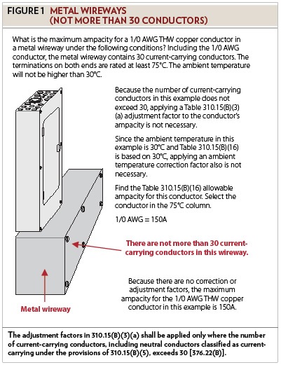
Requirements for conductors in auxiliary gutters and metal wireways are not the same as they are for conductors in raceways and cables. The second informational note in this section shows where these requirements can be found. Adjustment factors for conductors in sheet-metal auxiliary gutters are in 366.23(A), and adjustment factors for conductors in metal wireways are in 376.22(B). In auxiliary gutters and metal wireways, it is not required to derate the ampacity of conductors if the number of current-carrying conductors is 30 or less. For example, what is the maximum ampacity for a 1/0 AWG THW copper conductor in a metal wireway under the following conditions? Including the 1/0 AWG conductor, the metal wireway contains 30 current--carrying conductors. The terminations on both ends are rated at least 75°C. The ambient temperature will not be higher than 30°C. In accordance with 376.22(B), the adjustment factors in 310.15(B)(3)(a) shall be applied only where the number of current-carrying conductors, including neutral conductors classified as current-carrying under the provisions of 310.15(B)(5), exceeds 30. Because the number of current-carrying conductors in this example does not exceed 30, applying an adjustment factor to the conductor’s ampacity is not necessary. Since the ambient temperature in this example is 30°C and Table 310.15(B)(16) is based on 30°C, applying an ambient temperature correction factor also is not necessary. Because there are no correction or adjustment factors, look in Table 310.15(B)(16), in the 75°C column, for the allowable ampacity of this conductor. The maximum ampacity for the 1/0 AWG THW copper conductor in this example is 150 amperes (A) (see Figure 1).
Once the number of current-carrying conductors in a metal wireway (or auxiliary gutter) exceeds 30, the adjustment factors in Table 310.15(B)(3)(a) shall be applied. For example, what is the maximum ampacity for a 6 AWG THHN copper conductor in a metal wireway under the following conditions? Including the 6 AWG conductors, the metal wireway contains 34 current-carrying conductors. The terminations on both ends are rated at least 75°C. The ambient temperature will not be higher than 30°C.
Because the number of current-carrying conductors is more than 30, applying a Table 310.15(B)(3)(a) adjustment factor to the conductor’s ampacity is now required. Conductors with temperature ratings higher than specified for terminations shall be permitted to be used for ampacity adjustment, correction or both [110.14(C)]. If it is necessary to apply correction and/or adjustment factors, it is permissible to use the conductor’s ampacity straight out of the table, even if the ampacity is higher than what is allowed for the terminations. The temperature rating for a THHN conductor is 90°C. Although the terminations limit the ampacity to the 75°C column, it is permissible to use the ampacity in the 90°C column for correction and/or adjustment calculations. The allowable ampacity for a 6 AWG THHN conductor is 75A. The Table 310.15(B)(3)(a) adjustment factor for 34 current-carrying conductors is 40 percent. The maximum ampacity after applying the adjustment factor is 30A (75 0.40 = 30). Because there are more than 30 current--carrying conductors in this metal wireway, the maximum ampacity for the 6 AWG THHN copper conductor in this example is 30A (see Figure 2).
If the length of a raceway that contains current-carrying conductors is not more than 24 inches, applying a 310.15(B)(3)(a) adjustment factor is not necessary. In accordance with 310.15(B)(3)(a)(2), adjustment factors shall not apply to conductors in raceways having a length not exceeding 24 inches. For example, what is the maximum ampacity for a 2 AWG THW copper conductor in a raceway under the following conditions? There will be a total of eight current-carrying conductors in this raceway. There also will be an equipment grounding conductor in this raceway. The length of the raceway is 24 inches. The terminations on both ends are rated at least 75°C. The maximum ambient temperature will be 30°C. In accordance with Table 310.15(B)(16), the allowable ampacity for a 2 AWG THW copper conductor is 115A. It is not necessary to apply the 70 percent adjustment factor for eight current--carrying conductors because the length of this raceway does not exceed 24 inches. The maximum ampacity for the 2 AWG THW copper conductor in this example is 115A (see Figure 3).
Once the length of a raceway exceeds 24 inches and the number of current--carrying conductors is more than three, the adjustment factors in Table 310.15(B)(3)(a) shall be applied. For example, what is the maximum ampacity for a 2 AWG THW copper conductor in a raceway under the following conditions? There will be a total of eight current-carrying conductors in this raceway. There also will be an equipment grounding conductor in this raceway. The length of the raceway is 25 inches. The terminations on both ends are rated at least 75°C. The maximum ambient temperature will be 30°C. In accordance with Table 310.15(B)(16), the allowable ampacity for a 2 AWG THW copper conductor is 115A. The adjustment factor for eight current-carrying conductors is 70 percent. Multiply 115A by 0.70 (115 0.70 = 80.5 = 81). Before, when the length of the raceway was 24 inches, the maximum ampacity for the 2 AWG conductor was 115A. Now, because the raceway length is more than 24 inches, the maximum ampacity for this 2 AWG THW copper conductor is 81A (see Figure 4).
Next month’s column will continue the discussion of sizing conductors.
MILLER, owner of Lighthouse Educational Services, teaches classes and seminars on the electrical industry. He is the author of “Illustrated Guide to the National Electrical Code” and “The Electrician’s Exam Prep Manual.” He can be reached at 615.333.3336, [email protected] and www.charlesRmiller.com.
About The Author
Charles R. Miller, owner of Lighthouse Educational Services, teaches custom-tailored seminars on the National Electrical Code and NFPA 70E. He is the author of “Illustrated Guide to the National Electrical Code” and “Electrician's Exam Prep Manual.” He can be reached at 615.333.3336 and [email protected]. Connect with him on LinkedIn.


