Overview of NEC Article 430 and Its Application
Article 430 in the National Electrical Code (NEC) is titled “Motors, Motor Circuits and Controllers.” As the scope of the article states, it covers motors, motor branch-circuit and feeder conductors, motor branch-circuit and feeder protection, motor overload protection, motor control circuits, motor controllers, and motor control centers.
Figure 430.1 is like a table of contents to Article 430. The top half of this figure is a listing of all 14 parts as they appear in the article. The bottom half of Figure 430.1 shows the components or elements in relationship to the motor. Article 430 contains a number of provisions for sizing motor circuits and their components. Some of these calculation provisions end in a minimum size, and some end in a maximum size. For example, when sizing branch circuit conductors for motors, the result of the calculation is the conductor’s minimum ampacity. When sizing branch-circuit short-circuit and ground-fault protection for motors, the result of the calculation is the overcurrent protective device’s maximum ampere rating.
With most circuits, conductors are protected against overcurrent in accordance with their ampacities by overcurrent protective devices such as fuses and circuit breakers. Fuses and circuit breakers are not usually installed to provide overcurrent protection. Overload devices are usually installed to protect motors, motor-control apparatus and motor branch-circuit conductors against excessive heating due to motor overloads and failure to start. Fuses and circuit breakers are usually installed on motor circuits to protect the motor branch-circuit conductors, the motor control apparatus and the motors against overcurrent due to short circuits or ground faults. These devices are not intended to provide overload protection, which is instead achieved through properly rated motor overload devices as defined in NEC 430.32. This is why fuses and circuit breakers installed in motor circuits are not called overcurrent protective devices; they are called motor branch-circuit short-circuit and ground-fault protective devices. Requirements for motor overload protection are in Part III of Article 430.
Understanding Motor Branch-Circuit Short-Circuit and Ground-Fault Protection
Out in the field, motor overload protective devices are usually called “heaters” or “overloads.” Requirements for motor branch-circuit short-circuit and ground-fault protection are in Part IV of Article 430. Sections in Part IV include 430.51 through 430.58. In accordance with 430.52(A), the motor branch-circuit short-circuit and ground-fault protective device shall comply with 430.52(B) and either 430.52(C) or (D), as applicable. Section 430.52(B) states the motor branch-circuit short-circuit and ground-fault protective device shall be capable of carrying the motor’s starting current.
It is important to size fuses and circuit breakers in motor circuits so they open if there is overcurrent because of a short circuit or ground fault. It is also important to size fuses and circuit breakers in motor circuits so they do not open when the motor is starting. Locked rotor current or starting current is usually considerably higher than the current when the motor is running normally.
The title of 430.52(C) is “Rating or Setting.” It has seven subsections: (1) In Accordance with Table 430.52, (2) Overload Relay Table, (3) Instantaneous Trip Circuit Breaker, (4) Multispeed Motor, (5) Power Electronic Devices, (6) Self-Protected Combination Controller, and (7) Motor Short-Circuit Protector. As 430.52(D) states, torque motor branch circuits shall be protected at the motor nameplate current rating in accordance with 240.4(B).
Using NEC Table 430.52 to Calculate Maximum Protective Device Ratings
Percentages to calculate maximum rating or setting of motor branch-circuit short-circuit and ground-fault protective devices are in Table 430.52. This table provides percentages for non-time-delay fuses, dual-element (time delay) fuses, instantaneous-trip breakers and inverse-time breakers. When using this table, the rating or setting of the protective device shall not exceed the value of the motor’s the full-load current (FLC) multiplied by the percentage. Use Table 430.52 when sizing motor short-circuit and ground-fault protective devices for branch-circuits as well as for feeders. When determining motor FLC values, reference the appropriate voltage and horsepower in Tables 430.247–430.250 rather than nameplate current, which can vary by manufacturer.
There are two exceptions when using this table. The first exception under 430.52(C)(1) states, where the values for branch-circuit short-circuit and ground-fault protective devices determined by Table 430.52 do not correspond to the standard sizes or ratings of fuses, nonadjustable circuit breakers, thermal protective devices, or possible settings of adjustable circuit breakers, a higher size, rating or possible setting that does not exceed the next higher standard ampere rating shall be permitted. This exception can be used when calculating short-circuit and ground-fault protective devices for branch circuits supplying power to motor(s).
Example: Sizing a Circuit Breaker for a 10-HP, 208V, Three-Phase Motor
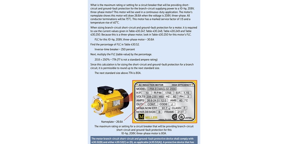
For example, what is the maximum rating or setting for a circuit breaker that will be providing short-circuit and ground-fault protection for the branch-circuit supplying power to a 10-horsepower (hp), 208-volt (V), three-phase motor? This motor will be used in a continuous duty application. The motor’s nameplate shows this motor will draw 26.6 amperes (A) when the voltage is 208V, three phase. All conductor terminations will be 75˚C. This motor has a marked service factor of 1.15 and a temperature rise of 40°C. When sizing branch-circuit short-circuit and ground-fault protection for a motor, use the current values given in tables 430.247, 430.248, 430.249 and 430.250. Because this is a three-phase motor, look in Table 430.250 for this motor’s FLC. The FLC for a 10-hp, 208V, three-phase motor is 30.8A.
Because the short-circuit and ground-fault protective device will be a circuit breaker, look in Table 430.52, and find the percentage under inverse-time breaker. Inverse-time circuit breakers are commonly used in motor applications because they allow a brief inrush current during motor startup before tripping, ensuring reliable operation without nuisance interruptions. Since this is a three-phase motor, look in the row for AC polyphase motors. The percentage to use to find the value of the rating or setting for a circuit breaker is 250 percent.
Next, multiply the FLC (table value) by the percentage. The value calculated is 77A (30.8 × 250% = 77). As shown in Table 240.6(A), 77 is not a standard ampere rating for a circuit breaker. Since this calculation is to determine the size branch-circuit short-circuit and ground-fault protection for a motor, it is permissible to round up to the next standard size. The maximum rating or setting for a circuit breaker that will be providing branch-circuit short-circuit and ground-fault protection for this 10-hp, 208V, three-phase motor is 80A (see Figure 1).
Determining Minimum Conductor Size for Continuous-Duty Motors
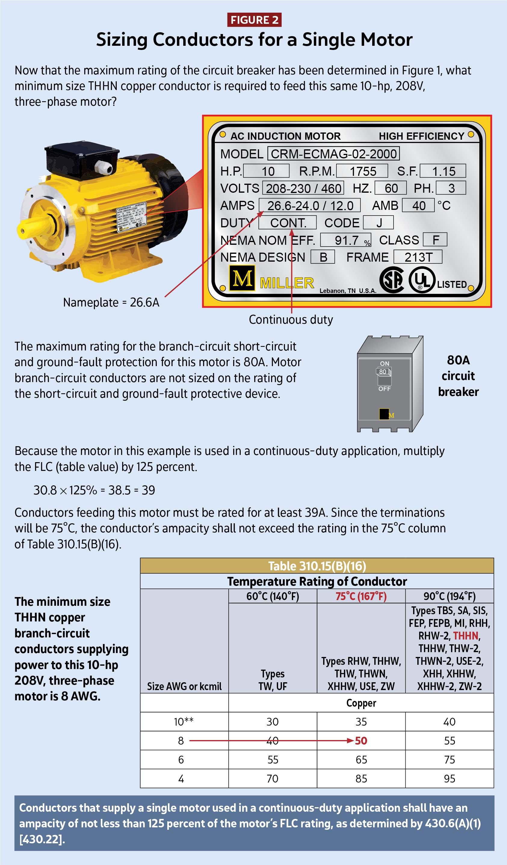
Now the maximum rating of the circuit breaker has been determined, what minimum size THHN copper conductor is required to feed this same 10-hp, 208V, three-phase motor? A common mistake at this point is to look in the 75°C column of Table 310.15(B)(16) for a conductor that has an allowable ampacity of at least 80A. A 4 AWG copper conductor in the 75°C column has an allowable ampacity or 85A, but this is not the correct size conductor.
This motor’s circuit breaker is not providing overcurrent protection. It is providing short-circuit and ground-fault protection. Proper coordination between the breaker, overload devices and conductor sizing ensures compliance with NEC 430.51–430.55 and maintains both safety and circuit reliability. Motor overload protective devices (heaters or overloads) sized in accordance with 430.32 will provide branch-circuit overload protection for this motor. In accordance with 430.22, a motor used in a continuous-duty application shall have an ampacity of not less than 125 percent of the motor FLC rating.
Because the motor in this example is used in a continuous-duty application, multiply the FLC by 125 percent. This 125% factor accounts for sustained operating temperatures in continuous-load conditions, preventing conductor overheating and ensuring long-term equipment performance.
The minimum ampacity for sizing the conductors supplying power to this motor is 39A (30.8 × 125% = 38.5 = 39). Select a copper conductor from the 75°C column of Table 310.15(B)(16). The minimum size THHN copper conductors supplying power to this 10-hp, 208V, three-phase motor is 8 AWG (see Figure 2).
Calculating Motor Overload Protection Ratings
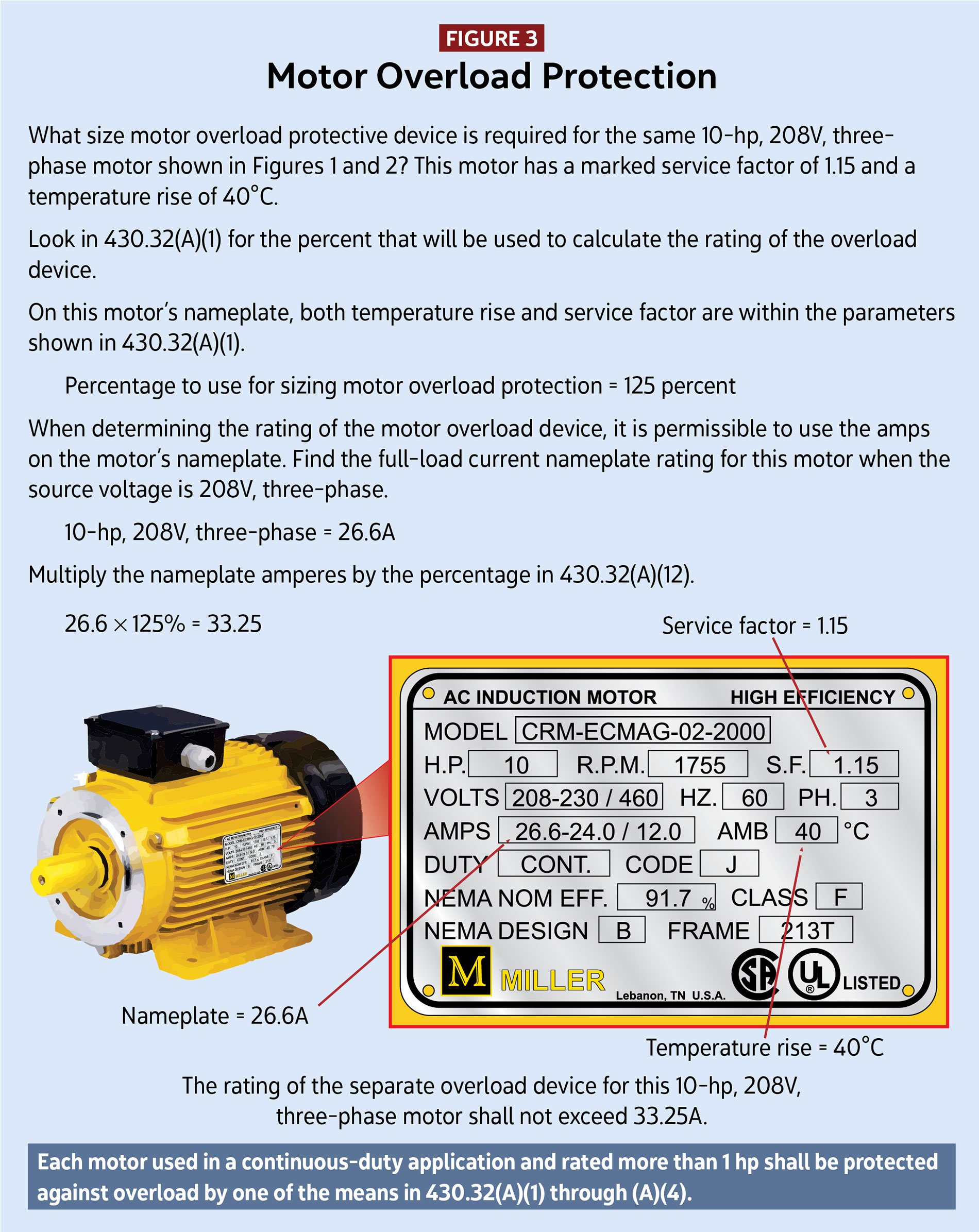
What size motor overload protective device is required for this 10-hp, 208V, three-phase motor? This motor has a marked service factor of 1.15 and a temperature rise of 40°C. In accordance with 430.32(A)(1), the percentage for motors with a marked service factor of 1.15 or greater as well as motors with a temperature rise 40°C or less is 125 percent.
When determining the rating of the motor overload device, it is permissible to use the amperes on the motor’s nameplate amperes. The nameplate FLC rating for this motor when the source voltage is 208V, three-phase, is 26.6A. The rating of the separate overload device for this 10-hp, 208V, three-phase motor shall not exceed 33.25A (26.6 × 125% = 33.25) (see Figure 3).
A note from Charles R. Miller
For 19 years, I have had the privilege of writing and illustrating Code in Focus, and this is my final one. I have made many wonderful connections through these 19 years because of this article. I want to thank everyone who is passionate enough about the National Electrical Code to take time out of your busy schedule to read my articles.
I also want to thank everyone at ELECTRICAL CONTRACTOR magazine for your dedication in making this magazine the best trade magazine in our industry.
<< Read Part VIII
About The Author
Charles R. Miller, owner of Lighthouse Educational Services, teaches custom-tailored seminars on the National Electrical Code and NFPA 70E. He is the author of “Illustrated Guide to the National Electrical Code” and “Electrician's Exam Prep Manual.” He can be reached at 615.333.3336 and [email protected]. Connect with him on LinkedIn.