You're reading an older article from ELECTRICAL CONTRACTOR. Some content, such as code-related information, may be outdated. Visit our homepage to view the most up-to-date articles.
210-5 Identification for Branch Circuits
Article 210 covers branch circuits, except those supplying only motor loads. Motor branch circuits are covered in Article 430. Last month’s In Focus concentrated on the multiwire branch-circuit provisions in Section 210-4. This month, we will cover the identification of branch-circuit conductors. Although it is mentioned in the article covering branch circuits, conductor identification also applies to services and feeders. Grounded conductors and equipment grounding conductors must be identified. The specifications pertaining to the identification of grounded conductors are actually listed in the article covering the use and identification of grounded conductors—Article 200. Therefore, instead of repeating the requirements, Section 210-5 references the specifications that are written elsewhere in the Code. Section 210-5(a) states that branch circuit’s grounded conductor must be identified in accordance with the specifications in 200-6. Section 200-6(a) covers No. 6 and smaller grounded conductors. These smaller conductors must be identified along the conductor’s entire length.
Unless meeting one of the stipulations in 200-6(a)(1) through (4), the identification must be by a continuous white or natural gray outer finish or by three continuous white stripes on other than green insulation. For many years, the National Electrical Code (NEC) has used the term “natural gray” as a color or finish to identify grounded conductors. In the 2002 edition of the NEC, the word “natural” was deleted. The new edition states that the colors can be white or gray. Unlike the smaller conductors, there are two options available for identifying sizes 4 AWG and larger insulated grounded conductors. The first option is to identify the conductor by a continuous white or natural gray outer finish or by three continuous white stripes on other than green insulation along its entire length. This is the same specification as stated for sizes 6 AWG and smaller grounded conductors. The second option permits encircling the conductor with a distinctive white marking at the terminations. Marking the conductor in this fashion must be done at the time of installation.
If conductors of different systems are installed in the same raceway, cable, box, auxiliary gutter, enclosure, etc., the grounded conductors of each system must be noticeably different. The grounded conductors from one system must meet the outer-covering specifications required by Section 200-6(a) or (b). Each other system grounded conductor must have an outer covering of white with a readily distinguishable different colored stripe running along the insulation. The stripe can be any color except green. This other system grounded conductor can also be identified by one of the other (and different) means specified in Section 210-6(a) or (b). For example, grounded conductors from two voltage systems are entering the same pull box, and all of the conductors are larger than No. 6. While one system is 208/120 volt, three-phase, four-wire, wye-connected; the other is 480/277 volt, three-phase, four-wire, wye-connected. The grounded conductor for the low voltage (208/120) system has been marked or identified by encircling white color-coding tape around the conductor. Gray color-coding tape has been used to identify the grounded conductor for the high-voltage (480/277) system. Depending upon the installation application, other means may be available for identifying the grounded conductor. For a complete listing, see Sections 200-6(a) through (e).
210-5(b) Equipment Grounding Conductor
Equipment grounding conductors must also be identified. As stipulated in Section 210-5(b), the identification of equipment grounding conductors must comply with Section 250-119. Unless required elsewhere in the NEC, equipment grounding conductors can be bare, covered, or insulated. If the grounding conductor is insulated (or covered) it must have an outer finish that is either green or green with one or more yellow stripes. Equipment grounding conductors are also permitted to be bare copper or aluminum. Sizes 6 AWG and smaller equipment grounding conductors must have an outer finish that is continuous along the conductor’s entire length. Marking only the exposed insulation on No. 6 and smaller conductors is not permitted. For example, a black, No. 10 insulated conductor cannot be identified as a grounding conductor by covering the ends with green electrical tape.
Three options are available for identifying insulated or covered equipment grounding conductors larger than No. 6 copper or aluminum. This identification must be permanent and must be done at the time of installation. Grounding conductors must be identified at each end and at every place where the conductor is accessible. All three of the following options can be completed after the conductors have been installed in the conduit or tubing. The first option permits stripping the insulation or covering from the entire exposed length of the grounding conductor. The insulation does not have to be removed from the entire length if the conductor is Size 4 AWG or larger. Stripping the conductor’s insulation from each end is not permitted for conductors smaller than No. 4. If the insulation is removed from No. 6 and smaller conductors, it must be removed along the conductor’s entire length. Coloring or painting the exposed insulation green is another option. The last option permits marking the exposed insulation with green tape or green adhesive labels. While it is a good practice to identify all conductors, grounding conductors must be identified at every point where the conductor is accessible. Where the conditions of maintenance and supervision guarantee that only qualified persons will service the installation, one or more conductors in a multiconductor cable can be identified at each end and at every place where the conductors are accessible. [250-119(b)]
Normally, a multiconductor cable that is smaller than No. 4 must have the equipment grounding conductor identified along the cable’s entire length. The three options permitted for this application are the same as the three options permitted for No. 4 and larger conductors. Conductors used as ungrounded (hot) conductors, whether used as single conductors or in multiconductor cables, must be finished in a way that is clearly distinguishable from grounded and grounding conductors. [310-12(c)]
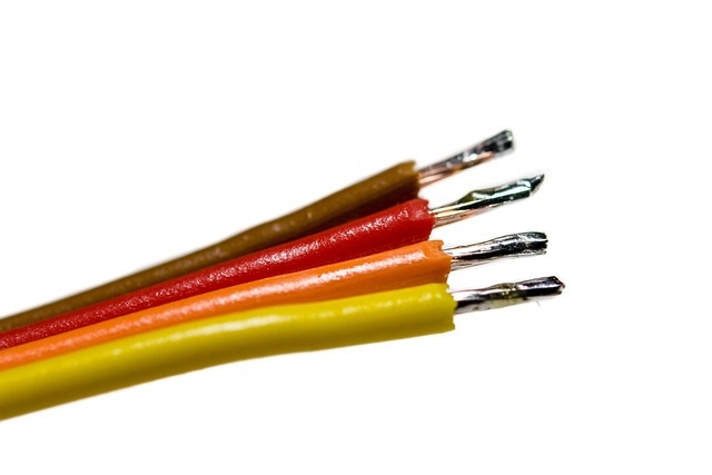
Ungrounded conductors (except for the high leg of a four-wire, delta connected system) can be any color other than white, natural gray, green, or green with yellow stripe(s). Although the colors for ungrounded (hot) conductors are not specified, there are some colors that are typically used. Generally, the color coding for a 208/120 volt, three-phase, four-wire, wye-connected system is black, red, and blue. The color coding typically used for a 480 volt, three-phase, four-wire system is brown, orange, and yellow. Some local (city, state, etc.) jurisdictions have adopted specific color coding requirements for conductors of different systems. Obtain a copy of these requirements (if any) for your area. The high-leg on a four-wire, delta-connected system must be durably and permanently marked by an outer finish that is orange in color or by other effective means. [230-56 and 384-3(e)]
Where the midpoint of one phase winding is grounded, one phase conductor will have a higher voltage to ground than the other two conductors. This phase or conductor is referred to as the high-leg.
About The Author
Charles R. Miller, owner of Lighthouse Educational Services, teaches custom-tailored seminars on the National Electrical Code and NFPA 70E. He is the author of “Illustrated Guide to the National Electrical Code” and “Electrician's Exam Prep Manual.” He can be reached at 615.333.3336 and [email protected]. Connect with him on LinkedIn.


