You're reading an older article from ELECTRICAL CONTRACTOR. Some content, such as code-related information, may be outdated. Visit our homepage to view the most up-to-date articles.
Though some rules can be overlooked without consequence, some are simply too important to not follow. Two rules, in particular, are at the fundamental analysis of all power systems: Ohm’s Law and Kirchoff’s Law. A month rarely goes by when someone doesn’t send me data from a power quality monitor that, if taken at face value, would discredit these two long-standing and proven rules. Of course, the flat-Earth theory was proven false, so these laws may someday follow suit. But it is best to assume that these rules still are true and that following them will lead to the correct explanation.
For example, I recently received data that showed a positive xxV DC bus going to negative zzV DC for a few milliseconds every yy milliseconds during certain times of the day (data was from a classified site; hence, I’ve obscured the exact numbers). The change in voltage levels occurred in microseconds. The current did not change abruptly during this time. In addition, one would imagine equipment powered off, such a voltage bus, would be “letting out the trapped smoke” that we often see during out-of-limits operation, particular with electronic components. Yet, none of this was noted.
Ohm’s Law says there are relationships among voltage, current and resistance. This has been extended from pure resistance to the term “impedance,” which accounts for inductance and capacitance that is found in most circuits of any size or capacity. The circuit’s current is directly proportional to the applied voltage and inversely proportional to the impedance of the circuit (I = V/Z). Or, the voltage drop across two points is equal to the current times the impedance (V = I × Z). Voltage also is referred to as the difference in potential energy between those two points, while current is the pressure pushing the electrons between those two points. Impedance, as the word sounds, is trying to impede or resist that pressure. For the same voltage potential, a higher impedance means less current is flowing between those two points and vice versa.
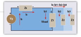
Kirchoff’s Laws are twofold: One involves voltage, and the other involves currents. The voltage rule is that the sum of the voltage drops around a closed loop will equal zero. In the figure above, tracing a route around the black portion of the circuit would say that Vs + Vload – Vg = 0. Note that since the generated voltage is the source rather than the sink or consumer of energy, the voltage drop has a negative sign relative to the direction of the current, as compared to all of the impedances, which have a positive to negative relationship in the voltage relative to the current direction. This is just a convention to also keep with the laws of physics, even in AC circuits where the current is really flowing in one direction during one half cycle and in the other direction during the other half cycle of the sine wave.
A simple math operation would make it more clear, namely Vg – Vs = Vload, with Vg standing for the generated voltage, Vs representing the voltage drop across the source impedance (all the transformers and wires leading up to the load) and Vload being the voltage remaining that appears across the load(s).
Since all three loads are in parallel in this example, the voltage across each is the same. Assuming the impedances (Z1, Z2 and Z3) are different, the current through each of the loads would be different by nature of Ohm’s Law, where Vload/Z1 = Iz1, Vload/Z2 = Iz2 and so on. Since the voltage is the same and impedance changes, so should the current being different.
Kirchoff’s other law deals with the currents, where the sum of the currents at any node or junction should equal zero. The current of the source (Is) is the same for the generator and the source impedance. However, when we get to node 1, where Z1, Z2 and Z3 connect to source impedance on the top branch and generator on the bottom branch, there are multiple paths for the current to flow. If we consider just node 1, the current flowing in from Is should equal the current leaving through Z1, Z2 and Z3. Again, a positive and negative sign convention is used to be consistent in the math. In this case, current entering the node is positive, and current leaving is negative. So Is – Iz1 – Iz2 – Iz3 = 0, or again with some quick math, Is = Iz1 – Iz2 – Iz3.
To put it in perspective, the source impedance is typically 10 to 50 times smaller than the load impedances. That way, most of the voltage from the generator ends up at the loads, doing work. In the example mentioned above, it would take a tremendous current in the opposite direction of normal for the voltage at the loads to reverse polarity and increase the magnitude of the voltage.
In addition, the wiring inductance and capacitance don’t let these things happen instantaneously. Those facts alone make it nearly impossible for the data to be real. And, the absence of smoke released (along with parts flying in the air) supports the idea that it is unlikely for this to be real. Instead, we look for other outside influences, such as very large electromagnetic fields, that can be coupled into the measuring inputs and make the measured values appear as such but not represent the true voltage levels on the xxV DC bus.
Once again, the rules were not broken. The simple explanation is the measurement included things happening in the air, not just on the voltage bus.
BINGHAM, a contributing editor for power quality, can be reached at 732.287.3680.
About The Author

BINGHAM, a contributing editor for power quality, can be reached at 908.499.5321.