You're reading an older article from ELECTRICAL CONTRACTOR. Some content, such as code-related information, may be outdated. Visit our homepage to view the most up-to-date articles.
It seems like more companies are performing arc flash hazard calculation studies (AFHCS) than ever before. One of the biggest attractions is that the study results provide just about everything you need to comply with many NFPA 70E requirements. Incident energy and arc flash boundary calculations, protective clothing and equipment ratings, arc flash warning labels, recommendations to reduce the hazard and even an updated single line diagram can all be provided as part of the study. With a list like this, you might be thinking, “What are we waiting for? How do I begin?”
Data collection and modeling
The largest effort is gathering the necessary data; it can often account for more than half of the entire study effort. The process gathers information on the equipment type, conductors, grounding, working distance, protective devices, utility company data and more.
With data in hand, the next step is to create a model or road map of the power system. Many computer programs can simplify this process by organizing the data and performing a series of complex calculations based on IEEE 1584—IEEE Guide for Arc Flash Hazard Calculations.
In addition to performing the study on normal operating conditions, it also may be necessary to evaluate alternate scenarios, such as a tie being open or closed. These scenarios can sometimes produce results that are worse than the normal case.
Short-circuit calculations
Short-circuit calculations are the next step. The traditional “bolted” short-circuit current is determined for each location and then used to calculate the arcing short-circuit current. The bolted condition assumes there is a solid connection at the point of the fault with no additional impedance. However, during an arc flash, the arc creates additional impedance that will cause the “arcing” short-circuit current to be less than the bolted current.
Duration and time-current curves
Not only is the severity of an arc flash related to the short-circuit current, it also depends on how long it lasts. Time-current curves are normally used to evaluate how long an upstream protective device takes to operate and clear the arc flash. These curves are graphical representations of how the device responds for a given amount of current.
If a time-current curve indicates the device may take a long time to operate, usually due to a very low short-circuit current, IEEE 1584 suggests capping the maximum time at 2 seconds, assuming a person will react and jump out of the way as long as there are adequate conditions.
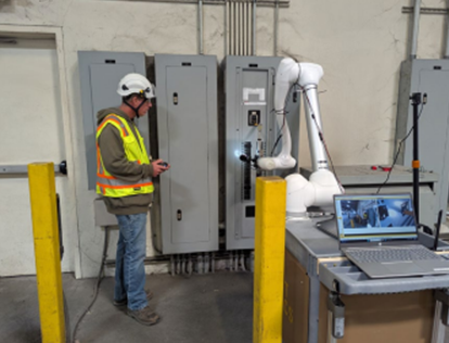
Incident-energy calculations
The most important component of the study is the incident-energy calculations, which are based on the arcing short--circuit current and arc flash duration. These calculations are used to predict the prospective incident energy that could reach a worker at a specific distance from the arc, known as the working distance. Workers must excercise caution because, if any part of them is closer than the working distance, the incident energy could be significantly greater than calculated.
Arc flash boundary
Another major component of the study is the arc flash boundary. Incident energy decreases exponentially with distance, and this boundary is defined as the distance from the arc flash where the incident energy falls to 1.2 cal/cm2. This value is considered the energy that can produce the onset of a second-degree burn; working closer than this distance requires the use of proper protection.
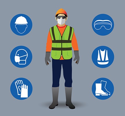
PPE selection and warning labels
Two final components of the study are the selection of appropriate protective clothing and equipment and creating arc flash warning labels.
Protective clothing and equipment must be selected with an arc rating that is sufficient for the calculated incident energy. Quite often, two arc ratings are specified. The first is for protection that is used on a more regular basis and is suitable for the majority of locations. The second rating is higher and is used at locations where the incident energy is much greater.
The AFHCS makes creating arc flash warning labels much easier because all of the necessary information is part of the study results. Many arc flash programs will automatically generate the labels by incorporating study results, including the incident energy, working distance, arc flash boundary and other important information directly into the labels.
It’s all there!
Although the results of the AFHCS can make complying with NFPA 70E much easier, it is important to recognize that the calculations are approximate at best and are based on theory and research. Workers can still be injured or worse during an arc flash. The safest approach will always be to place equipment in an electrically safe working condition.
PHILLIPS, founder of www.brainfiller.com and www.ArcFlashForum.com, is an internationally known educator on electrical power systems and author of “Complete Guide to Arc Flash Hazard Calculation Studies.” His experience includes industrial, commercial and utility systems, and he is a member of the IEEE 1584 Arc Flash Working Group. Reach him at [email protected].
About The Author

PHILLIPS, P.E., is founder of brainfiller.com and provides training globally. He is Vice-Chair of IEEE 1584 Arc Flash Working Group, International Chair of IEC TC78 Live Working Standards and Technical Committee Member of NFPA 70E. He can be reached at [email protected].