There is one tool that every tech needs and most already carry: the visual fault locator (VFL). A VFL is a bright red laser like a laser pointer with a port for inserting a fiber optic connector. The bright red light coupled into a fiber allows the tech to trace fibers, check for bending losses and find bad splices. It’s a gadget you can buy today for around $20, so every tech can afford to have one.
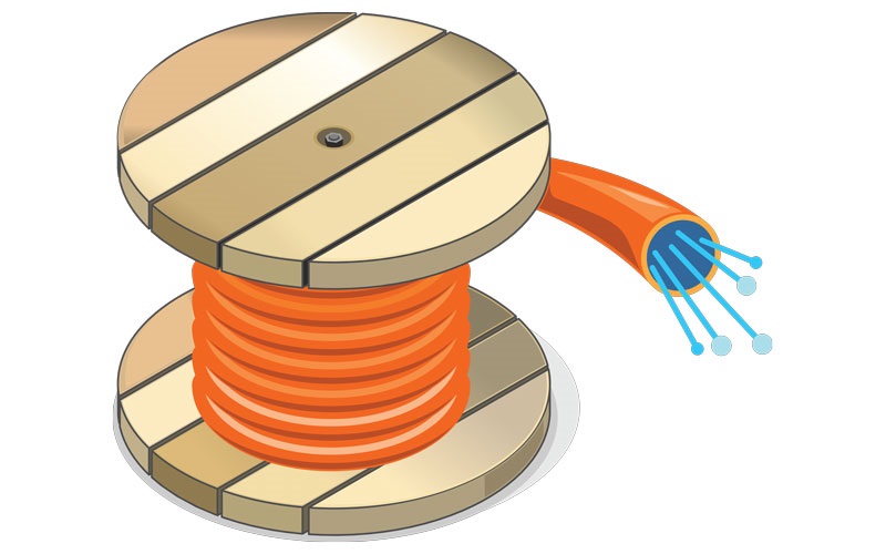
 Modern VFL the size of a laser pointer can illuminate an entire spool of fiber (photo by Eric Pearson).
The development of the VFL is another chapter of fiber optic history that I had a part in—a big part, in this case, since I created the product that introduced the VFL as a field tool for fiber optic installation. But the story did not start in the field; it began in an R&D laboratory.
The test equipment company I founded, FOTEC, started by creating instruments for measuring optical power and loss—optical power meters and test sources—aimed at field techs. But in conversations with manufacturers, we found a need for equipment for testing fiber optic components in labs and factories.
Our first project was an assembly and test station for single-mode 1,300-nm lasers for AT&T. While it was a manual instrument, it had provisions for being computerized. Both my head engineer and I had worked on automated test equipment for high-volume products like integrated circuits and PCs, so automation seemed like a logical design feature.
One of our first big automated test systems was a multichannel loss test set designed for Hughes. Hughes was developing a militarized fiber optic connector, rugged enough for tactical communications on the battlefield. To qualify the connector for military specifications, it was necessary to do environmental and life cycle testing of a large number of connectors.
The product we developed to Hughes’ specifications was a modular system with 8 channels of either power meters or sources per module. We could easily add modules to build systems with 100 channels of loss testers or more, and all the data was recorded on a PC.
While I was at the R&D labs at Hughes finalizing specs for their system, they showed me their lab. They were testing the loss of fiber connections on a big table with fiber running all around the table. To see what was going on, they were injecting light from a helium-neon red laser into the fiber with a microscope lens. With the laser, you could follow the fiber around the table and see the loss at connections. You could even see light lost where the fiber was bent too tightly.
I knew what I saw would be a superb tool for fiber techs in the field trying to troubleshoot an installation by finding bad splices, broken fibers or fibers bent too tightly. There was, however, a big problem—the laser was about 4 feet long, weighed about 100 pounds and required a 2,500V power supply. And it was very expensive. That was not exactly what you needed for a portable instrument.
The engineer told me that the Hughes division that made the lasers also made smaller ones. He gave me a contact at that division. It turned out that they had a smaller unit that was only about 2 inches in diameter, 18 inches long and weighed a couple of pounds. Its output was about 5W, which seemed sufficient when coupled into a fiber.
With some searching, we found a small 2,500V power supply for the laser that worked from either AC or 12V DC power. A small motorcycle battery would be sufficient to power the laser for a day and recharge quickly, making the unit portable for both indoor and outdoor use.
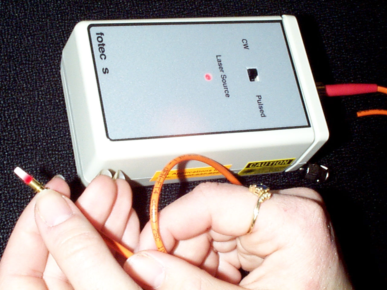
The next problem was coupling the laser into a fiber. We created a fixture to mount a fiber pigtail with a special graded index (GRIN) lens on one end that could focus the light into the fiber. The output coupled into the fiber was enough to light up a fiber so bends, splices and connections were easily visible.
(Later on, we switched to an expanded beam connector developed by Kodak, the camera company, but that’s another story.)
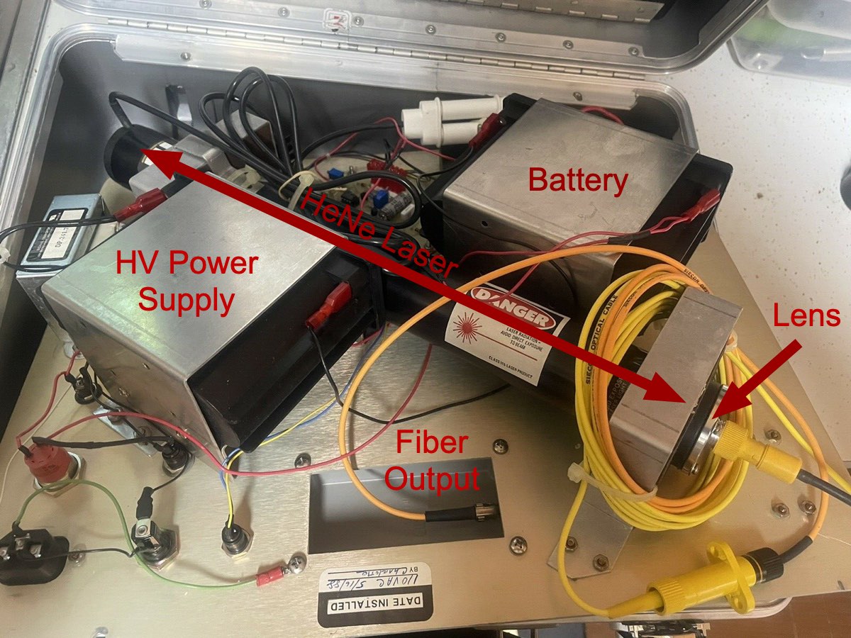 Components to the VFL were packed tightly in a rugged case.
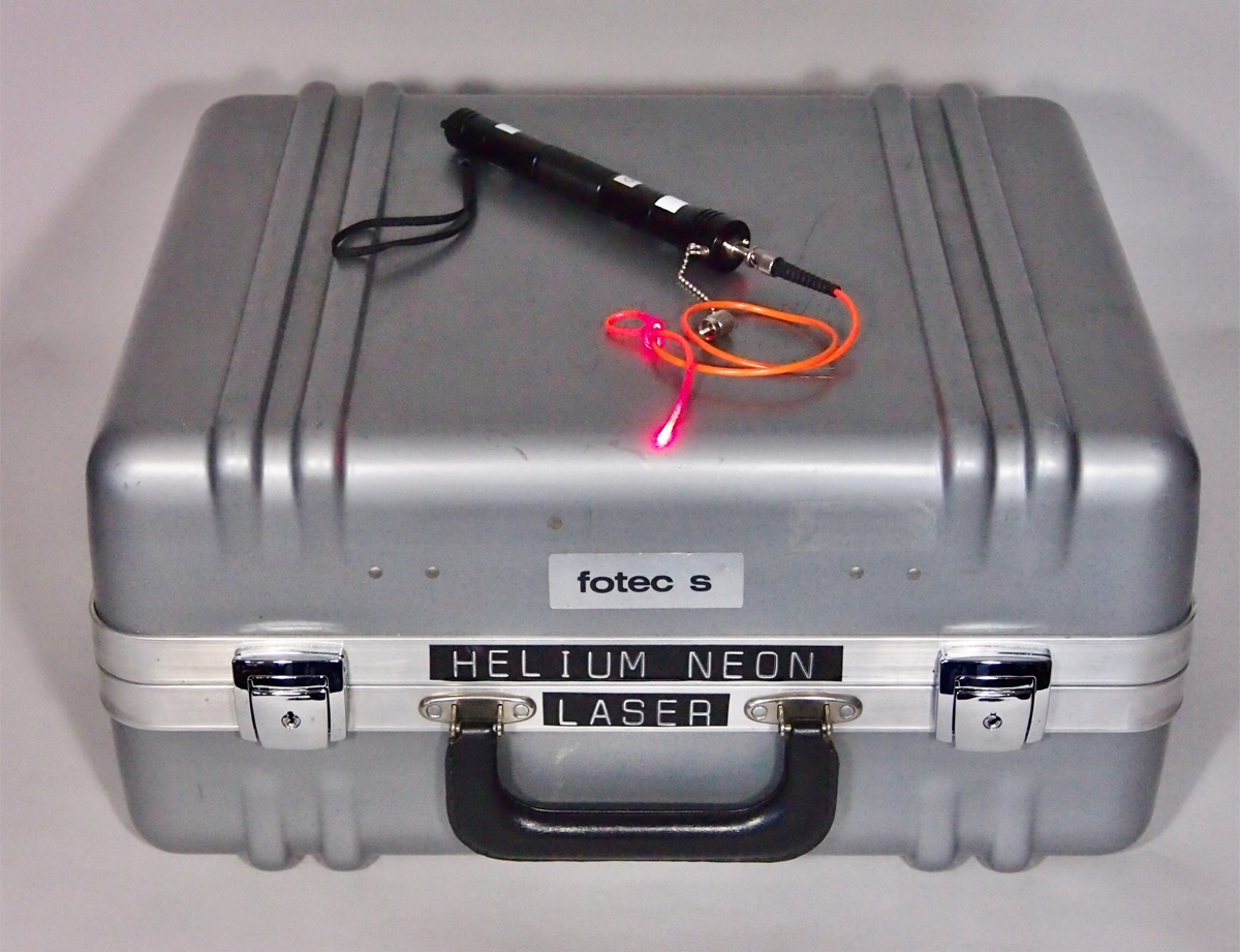
Then the final problem was packaging it for field use. We used a rugged, molded-plastic instrument case, mounted everything on a heavy aluminum plate with rubber insulators to withstand bumping around in the field or a truck and isolate the high-voltage components. For safety, we even used bolts that required a special tool so nobody could get into the unit. On the user safety side, there were shutters to prevent looking directly into the fiber optic connector, which could cause eye damage.
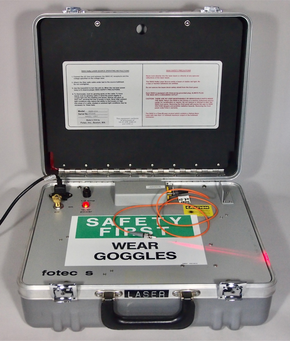
The original portable visual fault locator, the FOTEC S600.
That’s how we created the first portable VFL. It was the size of a suitcase, weighed around 20 pounds and sold for $3,200. Compare that to today’s handheld laser pointer type VFL that costs $20. But for the time, it was considered reasonable, even a bargain by some, since an OTDR was bigger, heavier and sold for $30,000–40,000.
When we introduced our VFL at a trade show, it was well received. We had many requests to demonstrate it in the field, the best way to prove its worth. One very interested group was MCI, which had just begun building their nationwide long-distance network.
I was invited to come to a remote town in Georgia where MCI had a big problem. They had a fiber with high loss at a splice, easily seen on an OTDR trace. They had already spliced the fiber several times, but that had not solved the problem.
When we coupled the VFL into the fiber, the problem was immediately obvious. The fiber had a crack about 6 inches from the splice, probably caused by being crushed by the cover of the splice tray. After the diagnosis, the problem was fixed quickly by cutting out the broken segment and splicing again.
MCI was impressed and started ordering one of our VFLs for every field crew. The word got around to other outside plant crews and they did the same.
Like all technology, new developments come at a rapid pace. The helium-neon laser VFL had a lifetime of about 5 years, before solid-state visible red lasers became available. Those were the same lasers developed for CD players and used in the millions, making them very inexpensive.
Solid-state red lasers helped shrink the VFL to a handheld instrument.
Soon we could buy pigtailled red lasers just like the lasers we used in our test sources at low prices. We put those in small, handheld instrument packages, creating a VFL that worked just as well, weighed less than one-tenth as much and sold for one-tenth the price.
Eventually, the makers of laser pointers got into the business also. Today, the laser pointer type VFL is equally as good and sells for 1/100th the price of the original instrument. Such is progress.
Tech advancements in VFLs over 40 years.
About The Author

HAYES is a VDV writer and educator and the president of the Fiber Optic Association. Find him at www.JimHayes.com.


