All fiber optic connectors should be inspected, cleaned if needed, and inspected again to ensure the cleaning was done thoroughly, before mating to another connector or inserting in a transceiver port. This applies to every connector, not just those you find on a patch panel—even including even new patchcords sealed in a plastic envelope.
First developments in fiber optic inspection microscopes
Since the diameter of an optical fiber is about the same as a human hair and the core of the fiber is even smaller, it’s obvious that inspecting fibers for dust, contamination and scratches requires magnification. Since the fibers we want to inspect are part of a connector, the magnifying device needs a way to hold the connector in just the right place to inspect the end of the ferrule. Those requirements led to the development of the fiber optic inspection microscope.
The first microscopes used for inspecting connectors were modified lab microscopes. Fitting a fiber optic connector to the microscope and lighting it properly was not simple, and, of course, these microscopes were not portable.
Adapting Panasonic’s microscope for fiber inspection
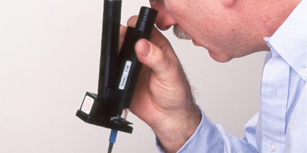
With the advent of field-terminated fiber optic connectors using adhesives and polishing the end of the fiber ferrule, portable microscopes also needed to be included in the termination kits provided by the connector manufacturers. Fortunately, a simple, inexpensive plastic microscope was available from Panasonic that could be modified for inspecting connectors. Practically every connector manufacturer used one of these microscopes or something similar.
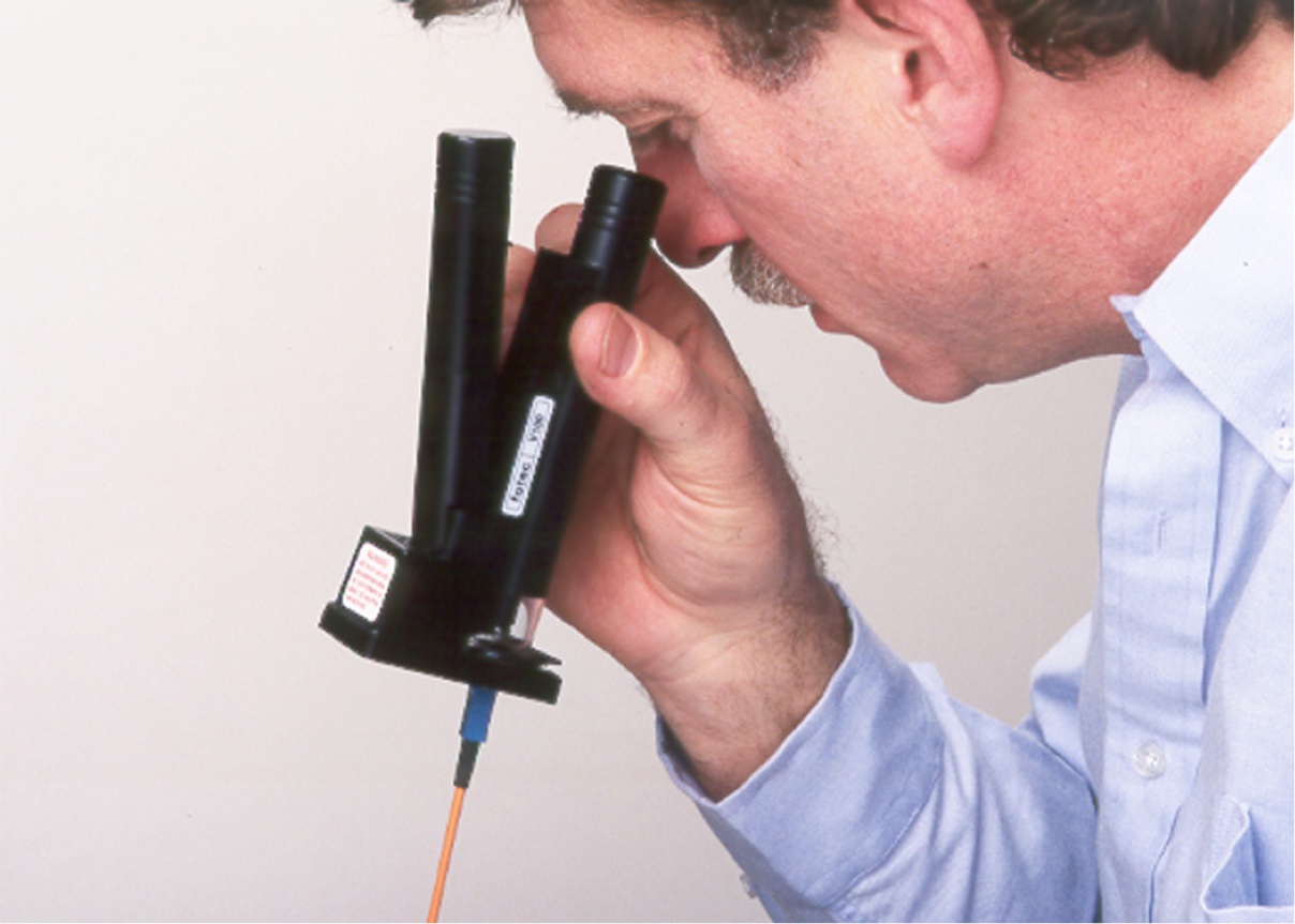
Modified Panasonic Fiber Optic Microscope, FOTEC V100 circa 1985, being used to inspect a fiber optic connector
This microscope was easily modified for inspecting fiber optic connectors. It had a built-in, battery-powered light to illuminate the connector and the stage for the microscope’s glass slides could be modified to hold a bracket for the connector. The bracket for the connector could even be used two ways: inspecting the connector directly and inspecting it at an angle, two views that gave better information on the quality of the connector ferrule.
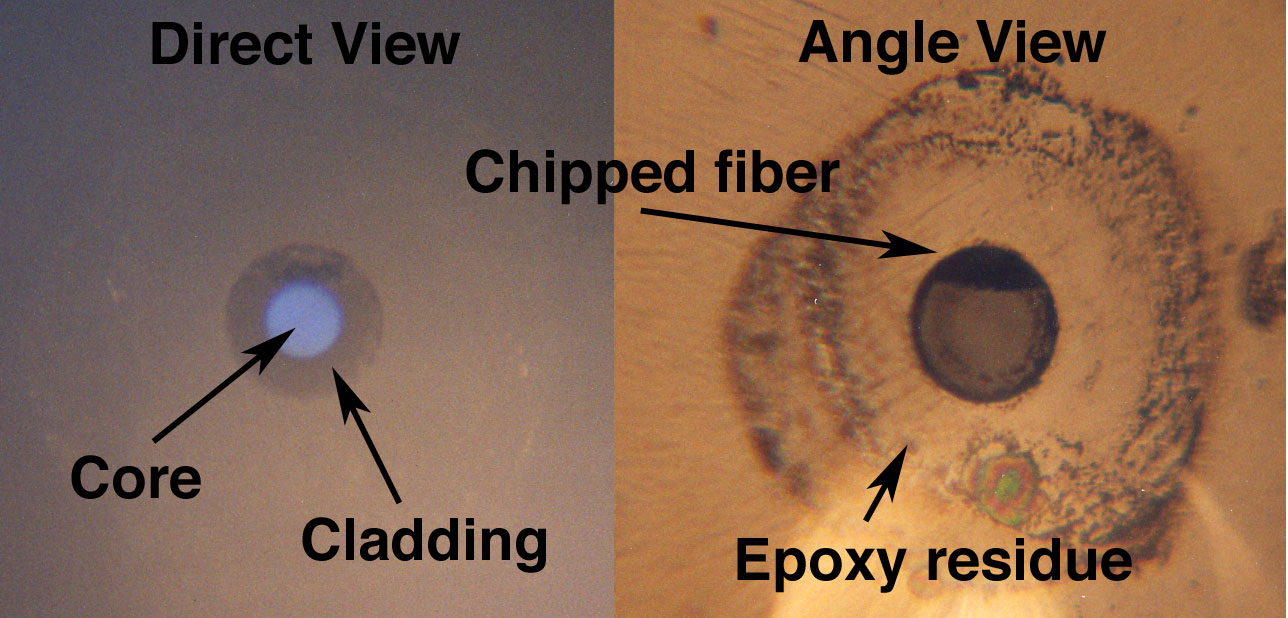
Direct and angle views of the same polished connector ferrule viewed in the Panasonic microscope, ca. 1985
The Westover microscope
Panasonic’s simple microscope served the industry well for many years, until a company went to an optical equipment manufacturer and had a special microscope designed for fiber optics. The Westover microscope was a much better tool for inspecting fiber optic connectors.
The Westover (now VIAVI) microscope was used to inspect fiber optic connectors, circa late 1990s
This microscope offered many better features compared to the Panasonic version. It was more rugged and had much better optics. Versions are available for 100x, 200x and 400x magnification. The availability of various magnification powers caused some disagreements about the “right” magnification, with some complaining that 400x was too high, limiting the field of view and exaggerating the surface condition, while others said 100x was inadequate for inspecting single-mode polishing. It was mostly opinion as all worked well. This microscope offered direct lighting of the connector through the optical path as well as oblique lighting with an LED off to the side. Adapters for connectors were more stable and precise.
Advancements in fiber inspection: Video microscopes
The next step forward for connector inspection was the video microscope. This was a video camera mated to a microscope with fixtures for connectors. It displayed the image on a dedicated video screen or was attached to a PC, which displayed the image.
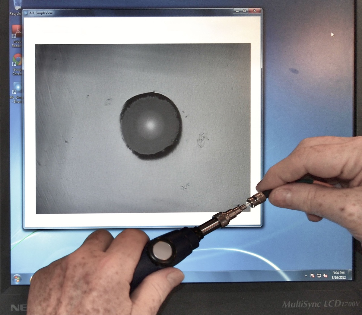
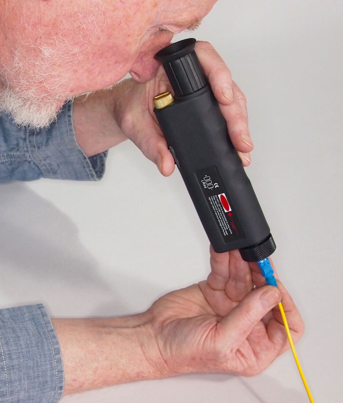
Video microscope probe for PC, circa 2000, being used to inspect a fiber optic connection
The video microscope was a major advance in optical inspection of connectors. It allowed changing magnification to view most of the connector ferrule or zoom in on the fiber, and using image analysis to help find dirt, contamination and defects.
Video microscopes also solved a problem for optical microscopes, which could focus potentially harmful invisible infrared light in the fiber into the eye. That was not a problem with a video microscope, where the user only saw an image of the connector on a screen.
Benefits of video microscopes for fiber inspection
Video microscopes allow automating inspection, producing reports like the one below that can be saved for documentation of properly cleaned connectors and used for future reference.
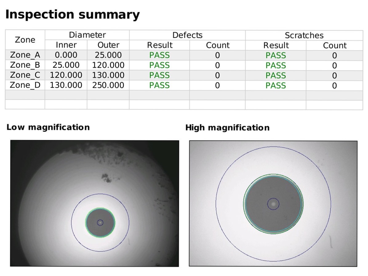
Automated fiber optic connector inspection report generated by a video microscope
ISO/IEC-61300-3-35 standard for fiber inspection
An international standard for inspection, ISO/IEC-61300-3-35, was developed to automate the inspection using video microscopes, specifying the number of defects allowable in four zones around the core. Many video microscopes include testing to this standard.
Inspection of connectors for dirt and contamination is generally limited to a small area around the fiber itself. The size of the area covered in the IEC 61300-3-35 standard for connector inspection is shown in the photo below. The area inside the red circle in the photo below shows the total area covered in this international standard for connector inspection used for automatic inspection by video microscopes.
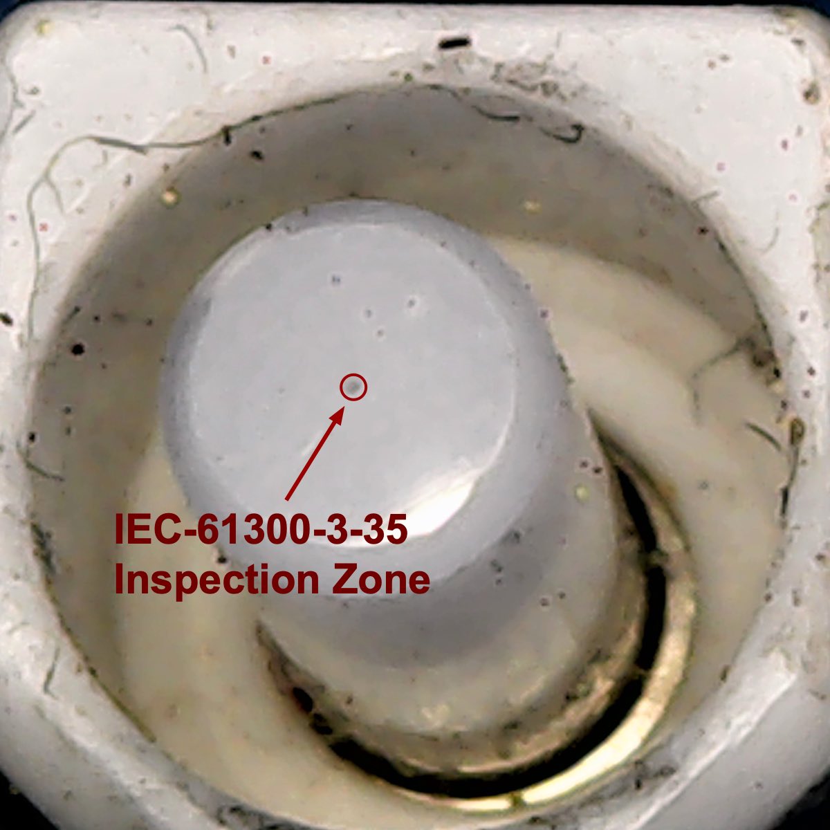 SC fiber optic connector wide-field view compared to the typical inspection region of a video microscope
However, there is a lot more area on the end of the connector ferrule, plus the sides of the ferrule, which can get dirty from mating cycles, and the inside of the connector body, which can transfer dirt to the connector ferrule. Note that this connector has a clean ferrule and a very dirty connector body. The industry has not dealt with this aspect of connector inspection and cleaning yet, but some in the industry are working on it.
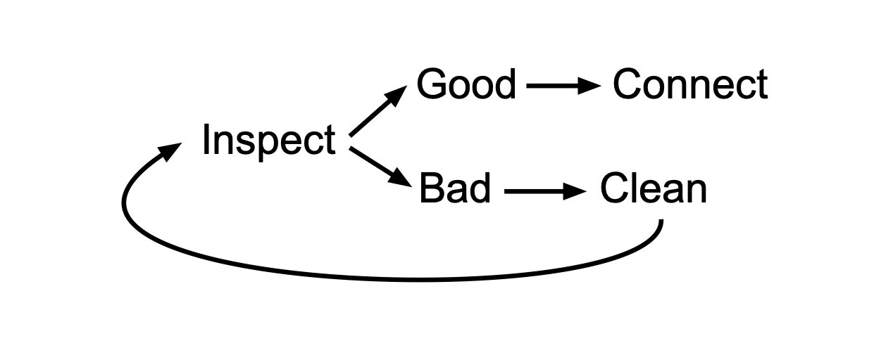
Remember: Inspect, clean, then inspect again to ensure proper cleaning of fiber optic connections.
About The Author

HAYES is a VDV writer and educator and the president of the Fiber Optic Association. Find him at www.JimHayes.com.