This article continues the series on the technology of fiber optics. This article will discuss the development of the fiber optic connector, which is one of the major developments that facilitated the rapid growth of fiber optics in communications.
I was introduced to fiber optics at Bell Labs by the researchers inventing a lot of the technology needed to convert the phone network into fiber optics. At Bell Labs, I met the scientists and engineers who were developing the equipment to digitize phone lines, lasers needed for transmitters and various components needed for the cable plant like cables, splices and connectors.
One of the most interesting labs I visited at Bell Labs was the lab of engineer Jack Cook, where fiber optic connectors were being developed.
Cook explained to me the problems with creating connectors for optical fibers. Imagine joining two human hairs precisely, then being able to disconnect and reconnect them hundreds of times. It required precision measured in microns (0.001 mm). And there are a number of ways that alignment of the two fibers can cause loss.
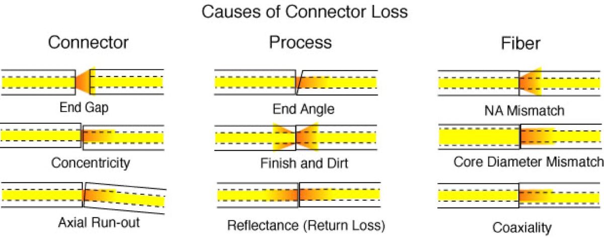
The many facets of connector loss attributed to the connector itself, the termination process and variations in the optical fiber.
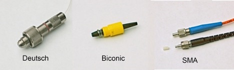
The first fiber optic connectors used a variety of methods to try making a low loss connection, resulting in a great deal of variation in connector styles and sizes.
The Deutsch 1000 connector was one of the first connectors and probably the biggest and heaviest. It was machined from stainless steel and held a cleaved fiber in a clamp inside the connector. When mated, the spring-loaded nosepiece pushed back to expose the fiber, which was aligned in a plastic lens filled with index matching fluid. With luck, it could be a 1-decibel (dB) loss connection for multimode fiber and was never used on single-mode fiber.
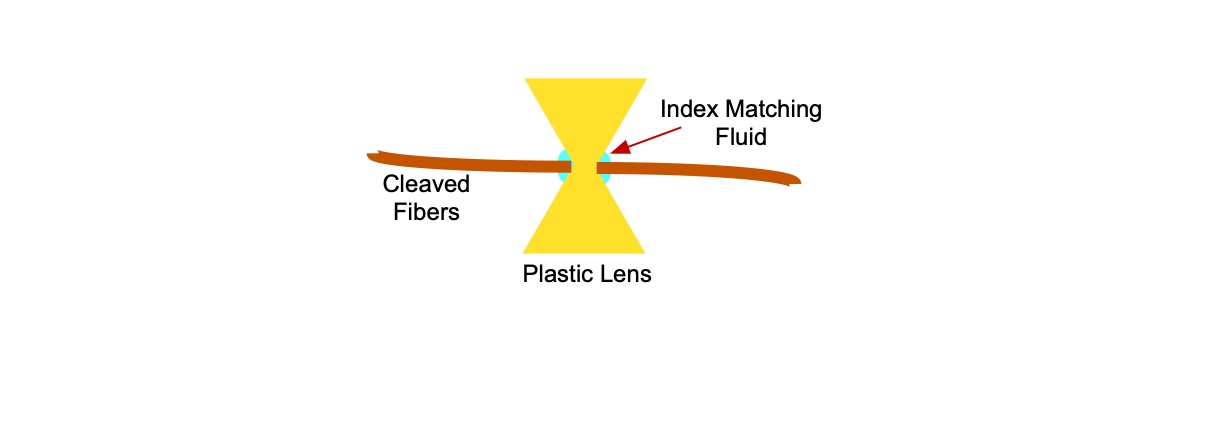
The idea of aligning bare fibers and using index matching fluid was used in many connectors over the years. TRW used this technique using glass rods to align the fibers. Even 3M tried it as late as 2000 in their Volition connector, but none of these gained widespread usage.
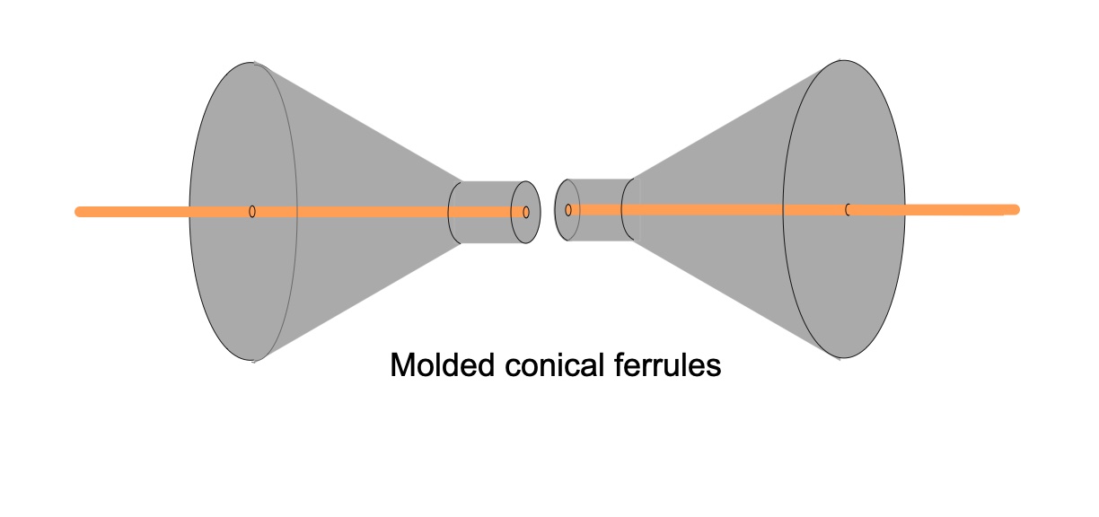
Cook’s solution at Bell Labs was the Biconic connector, a molded connector of glass-filled plastic that used cones to align the fibers. A factory-terminated Biconic connector could achieve losses of 0.5–1 dB with multimode fiber. The connector was not keyed to allow rotating it for tuning to minimize loss, so there had to be a gap between the ends of mated connectors to prevent scratching.
Single-mode fiber was a big problem for the Biconic. Aligning the fibers required machining the conical ferrules and angling the tip to prevent reflections. Even so, losses below 1 dB were difficult to achieve.
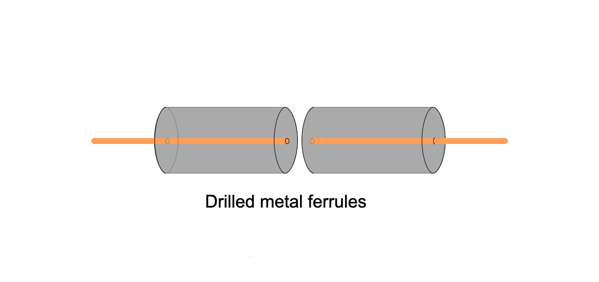
The SMA connector used machined cylindrical stainless-steel ferrules drilled with a 125-micron (0.005 inch) hole at the end and aligned in a drilled stainless-steel tube. Alignment was determined by many variables of the machining process, so typical losses for multimode fiber were around 0.5–1 dB. Like the Biconic, you could rotate the connector to tune connectors to minimize loss. A version of the SMA used a ferrule machined to a smaller diameter on the end and aligned with a plastic tube for better alignment, but the SMA was never useful for single-mode fiber.
Other methods of aligning fibers were tried but discarded. One approach was to minimize the alignment problem by using lenses to expand the beam emerging from the fiber into a larger size beam. Several companies tried expanded beam connectors, and Eastman Kodak used molded lens technology from its disc cameras.
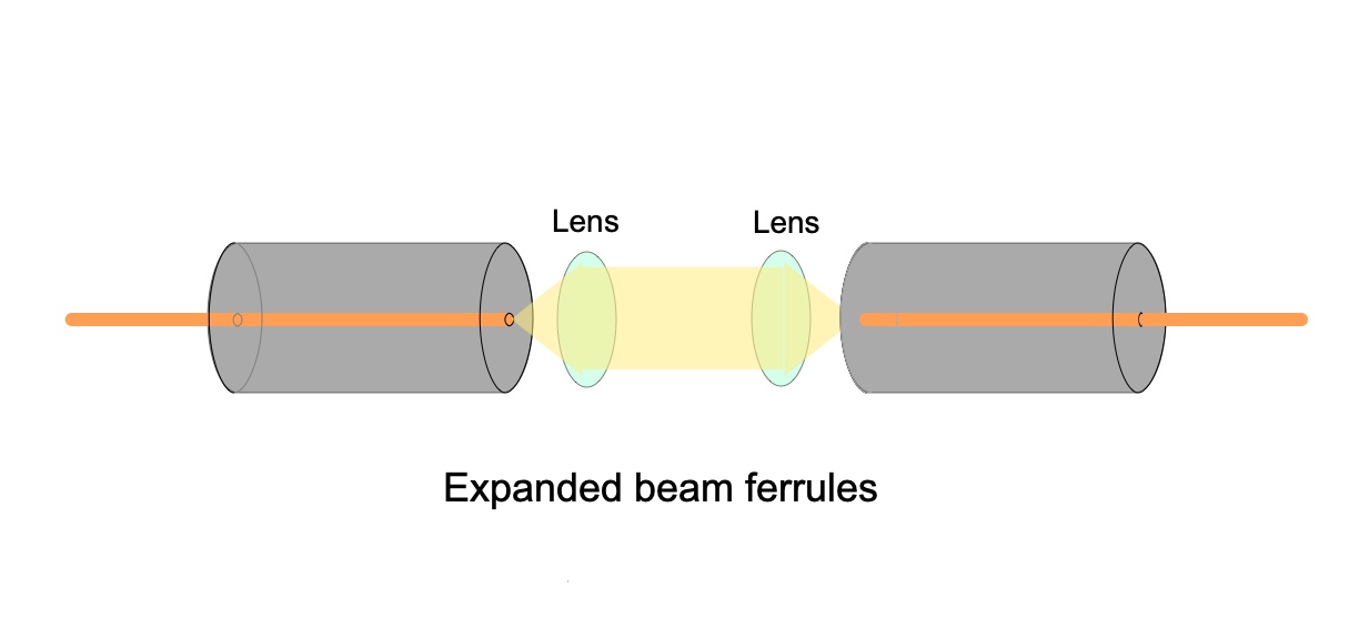
Expanded beam connectors are still in use today, primarily for large, multifiber military fiber optic connectors. These connectors are designed to be used in dirty environments and the expanded beam is less affected by dirt.
Everything changed in the mid-1980s. A company well-known for their ceramic packages for semiconductors and integrated circuits, Kyocera, worked with NTT (Nippon Telephone and Telegraph) and NEC (Nippon Electric Corp.) to develop the ceramic ferrule for connectors.
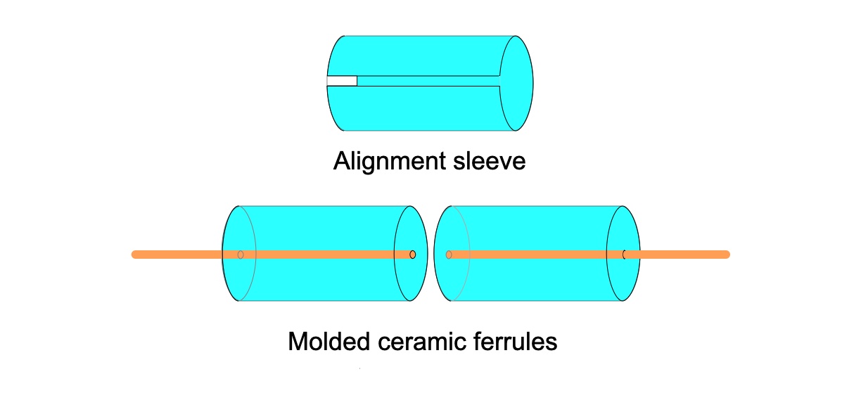
Ceramic ferrules had the dimensional precision needed for all fibers. It was the breakthrough needed for singlemode fiber. These ferrules were the connector needed for adoption of single-mode in telecommunications systems.
The first connectors to use the ceramic ferrules were the NEC D4 and the NTT FC, followed quickly by the AT&T ST and the SC.
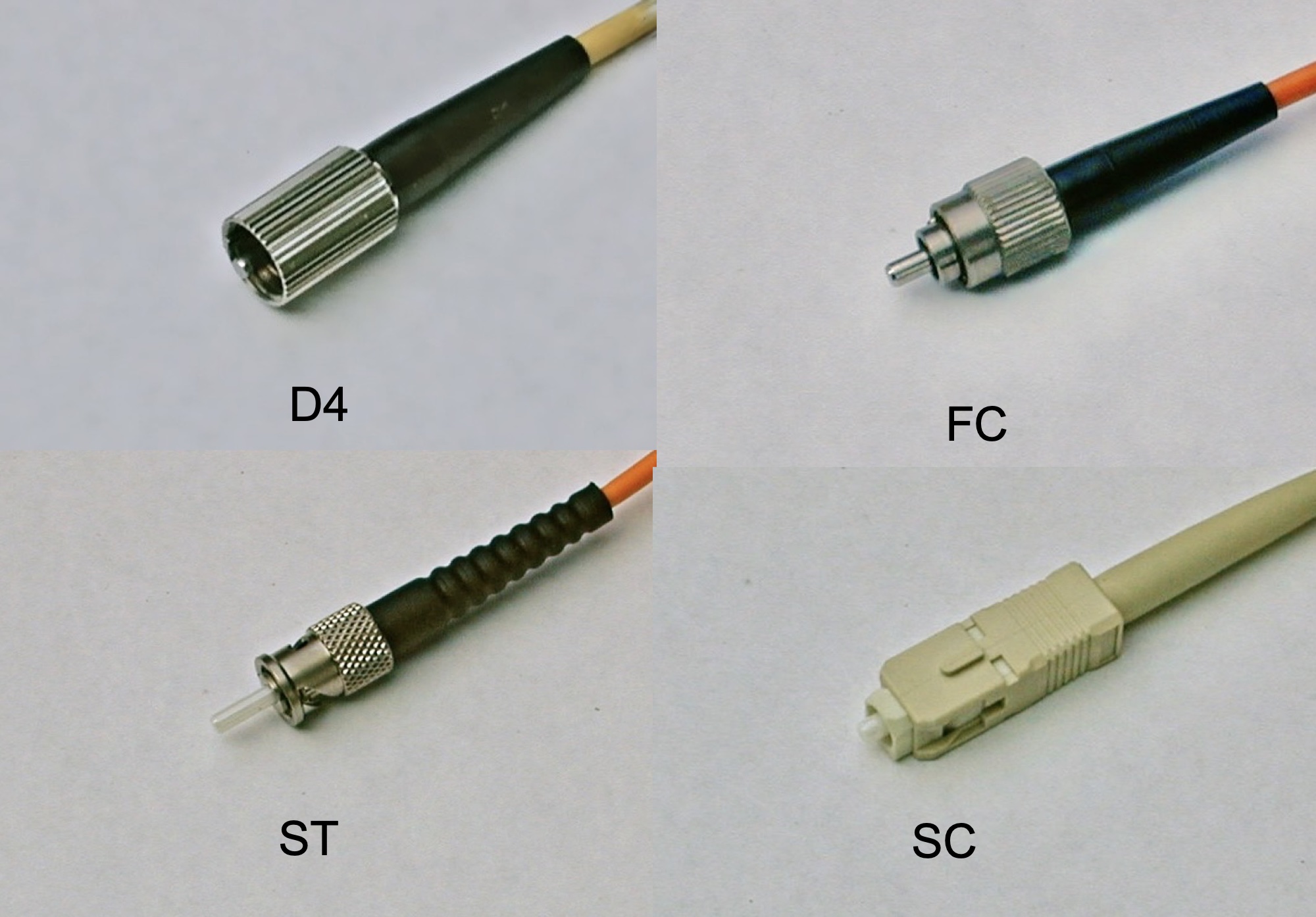
First connectors to use ceramic ferrules
There is a plaque in Japan commemorating this achievement.
Besides providing the precise alignment needed for single-mode fibers, ceramic ferrules had another major advantage. Because they are very hard and wear-resistant, they could be polished with a dome on the end, allowing fibers to mate in physical contact, reducing loss and reflectance. In addition, by polishing the end of the ferrule at an 8-degree angle, reflectance could be almost totally eliminated, which was a major advantage in very-high-speed fiber optic systems, especially those using dense wavelength division multiplexing (DWDM.)
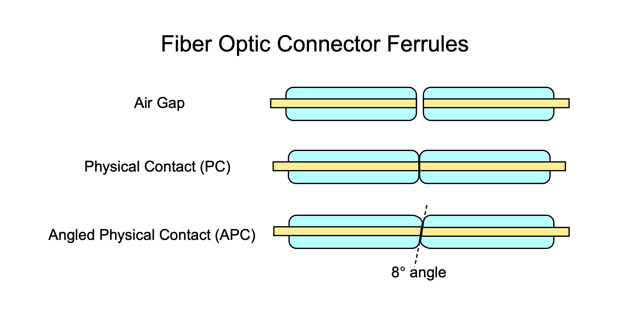
Three types of connectors, air gap like the original Biconic, and PC and APC connectors, were made possible by ceramic ferrules.
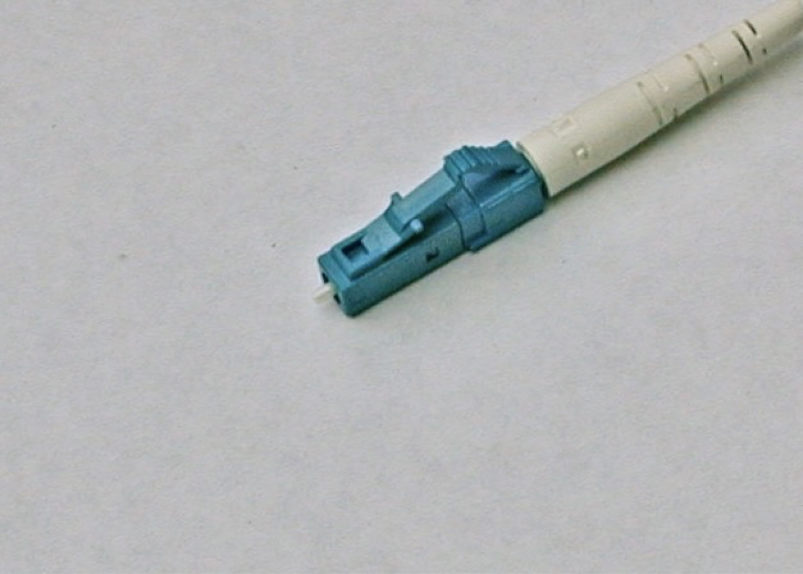
Since the invention of the ceramic ferrule in the mid-1980s, most fiber optic connectors have used them, primarily with 2.5-mm ferrules. Around 2000, several small form factor connectors were introduced with a smaller ceramic ferrule with a diameter of 1.25 mm. The LC connector, one of the most popular ones today, uses this small ferrule.
One thing has not changed in all these years: most connectors are still made by using a heat-cure epoxy to glue the fiber in the ferrule and carefully polishing the fiber. But most are made in a factory producing pigtails and cables. Field termination is now mainly done by splicing factory-made pigtails or splice-on connectors on the end of the fiber optic cable.
About The Author

HAYES is a VDV writer and educator and the president of the Fiber Optic Association. Find him at www.JimHayes.com.