You're reading an older article from ELECTRICAL CONTRACTOR. Some content, such as code-related information, may be outdated. Visit our homepage to view the most up-to-date articles.
The National Electrical Code (NEC) is revised every three years. The renumbering of Table 310.16 to Table 310.15(B)(16) was a significant change in the 2011 edition. (Note, for number changes to other ampacity tables, see Article 310 of the 2011 NEC.) Besides the number change at the top of the page, there is another noticeable difference at the bottom of the page: the ambient temperature correction factors are no longer below the conductor ampacities.
They are now in Tables 310.15(B)(2)(a) and (b). The correction factors in Table 310.15(B)(2)(a) are based on a temperature of 30°C, and the correction factors in Table 310.15(B)(2)(b) are based on 40°C.
Since there are now two correction factor tables, don’t be confused about which table to use. Selecting the correct table is easy. The last sentence in the headings of the tables specifies which ambient temperature the ampacities are based on. Simply match the ampacity table temperature with either Table 310.15(B)(2)(a) or (2)(b). For example, the last sentence in the headings of Table 310.15(B)(16) states that the ampacities in this table are based on ambient temperature of 30°C. Therefore, use the ambient temperature correction factors in Table 310.15(B)(2)(a) with Table 310.15(B)(16).
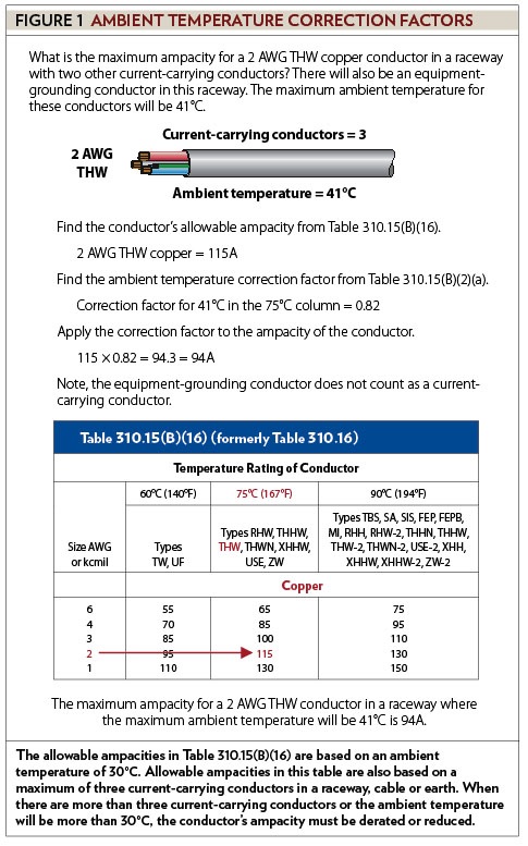
Article 100 defines ampacity as the maximum current, in amperes (A), that a conductor can carry continuously under the conditions of use without exceeding its temperature rating. One of the “conditions of use” is ambient temperature. As previously mentioned, the allowable ampacities in Table 310.15(B)(16) are based on an ambient temperature of 30°C. Allowable ampacities in this table also are based on a maximum of three current-carrying conductors in a raceway, a cable or earth. When there are more than three current-carrying conductors or the ambient temperature will be more than 30°C, the conductor’s ampacity must be derated or reduced. For example, what is the maximum ampacity for a 2 AWG THW copper conductor in a raceway with two other current-carrying conductors? There will also be an equipment-grounding conductor in this raceway. The maximum ambient temperature for these conductors will be 41°C. Start by finding the conductor and the listed ampacity in Table 310.15(B)(16). The allowable ampacity for a 2 AWG THW copper conductor is 115A. Because the ambient temperature is other than 30°C, the table ampacity must be multiplied by the appropriate ambient temperature correction factor. Type THW conductor has a temperature rating of 75°C; therefore, look for the correction factor in the 75°C column of Table 310.15(B)(2)(a). Follow down the 75°C column, and find the row that intersects with the maximum ambient temperature. The correction factor, in the 75°C column, for an ambient temperature of 41°C is 0.82. Next multiply 115A by 0.82 (115 x 0.82 = 94.3 = 94). The maximum ampacity is 94A for a 2 AWG copper THW conductor in a raceway where the maximum ambient temperature will be 41°C (see Figure 1).
Although the raceway contains four conductors, there are only three current-carrying conductors because grounding and bonding conductors do not count as current-carrying conductors. Therefore, there is no adjustment factor for current-carrying conductors.
As I previously discussed in this series on sizing conductors, temperature ratings of conductors must be considered. In accordance with 110.14(C), the temperature rating associated with the ampacity of a conductor shall not exceed the lowest temperature rating of any connected termination, conductor or device. The next sentence is important when applying temperature correction and/or adjustment factors. Conductors with temperature ratings higher than specified for terminations shall be permitted to be used for ampacity adjustment, correction or both [110.14(C)]. This rule means, if it is necessary to apply correction and/or adjustment factors, it is permissible to use the conductor’s ampacity straight out of the table, even if the ampacity is higher than what is allowed for the terminations.
For example, what is the maximum ampacity for a 6 AWG THHN conductor in a raceway with two other current--carrying conductors? The terminations on both ends of these conductors are rated at least 75°C. The maximum ambient temperature for these conductors will be 48°C. There also will be an equipment-grounding conductor in this raceway. The temperature rating for a THHN conductor is 90°C. Although the terminations limit the ampacity to the 75°C column, it is permissible to use the ampacity in the 90°C column for correction and/or adjustment calculations. The allowable ampacity for a 6 AWG THHN conductor is 75A. The Table 310.15(B)(2)(a) correction factor, in the 90°C column, for an ambient temperature of 48°C is 0.82. The maximum ampacity after applying the adjustment factor is 62A (75 x 0.82 = 61.5 = 62). In accordance with 110.14(C)(1)(a)(3), the ampacity for this conductor shall not exceed the ampacity listed in the 75°C column, which is 65A. Although the temperature limitations of the terminals will allow for an ampacity of 65A, the ambient temperature will not. Because of the ambient temperature, the maximum ampacity for the 6 AWG conductors in this example is 62A (see Figure 2).
While it is permissible to use the higher ampacity when applying correction and/or adjustment factors, it is still a violation to exceed the lowest temperature rating of any connected termination, conductor or device. For example, what is the maximum ampacity for a 3/0 AWG THHN conductor in a raceway with two other current-carrying conductors? The terminations on both ends of these conductors are rated at least 75°C. The maximum ambient temperature for these conductors will be 35°C. There will also be an equipment-grounding conductor in this raceway. The allowable ampacity for a 3/0 AWG THHN conductor is 225A. The Table 310.15(B)(2)(a) correction factor, in the 90°C column, for an ambient temperature of 35°C is 0.96. The maximum ampacity after applying the adjustment factor is 216A (225 x 0.96 = 216).
By considering only the ambient temperature, the maximum ampacity for this conductor is 216A. But, ambient temperature is not the only provision that must be considered. In accordance with 110.14(C)(1)(b)(2), the ampacity for this conductor shall not exceed the ampacity listed in the 75°C column. The ampacity for a 3/0 AWG conductor in the 75°C column of Table 310.15(B)(16) is 200A. Therefore, the maximum ampacity for the 3/0 AWG conductors in this example is 200A (see Figure 3).
Next month’s article will continue the discussion of sizing conductors.
MILLER, owner of Lighthouse Educational Services, teaches classes and seminars on the electrical industry. He is the author of “Illustrated Guide to the National Electrical Code” and “The Electrician’s Exam Prep Manual.” He can be reached at 615.333.3336, [email protected] and www.charlesRmiller.com.
About The Author
Charles R. Miller, owner of Lighthouse Educational Services, teaches custom-tailored seminars on the National Electrical Code and NFPA 70E. He is the author of “Illustrated Guide to the National Electrical Code” and “Electrician's Exam Prep Manual.” He can be reached at 615.333.3336 and [email protected]. Connect with him on LinkedIn.