You're reading an older article from ELECTRICAL CONTRACTOR. Some content, such as code-related information, may be outdated. Visit our homepage to view the most up-to-date articles.
NEC Requirements for Branch-Circuit, Feeder and Service Conductor Ampacity
Whether conductors are supplying power to branch circuits, feeders or services, the ampacity must not be less than the load, ensuring that conductors remain within their thermal limits under expected operating conditions and preventing insulation damage or overheating. The load can be an actual load, or it can be calculated in accordance with the requirements in Article 220 of the National Electrical Code (NEC).
Requirements for branch circuits are in Article 210, feeder requirements are in Article 215, and requirements for services are in Article 230. One common stipulation with all these conductors is that the ampacity of the conductors must equal or exceed the load. Branch-circuit conductors shall have an ampacity not less than the maximum load to be served [210.19(A)(1)]. Feeder conductors shall have an ampacity not less than required to supply the load as calculated in parts III, IV and V of Article 220 [215.2(A)(1)]. Service conductors (overhead and underground) shall have sufficient ampacity to carry the current for the load as calculated in accordance with Article 220 and shall have adequate mechanical strength [230.23(A) and 230.31(A)].
Using Table 310.15(B)(16) and Temperature Limitations When Sizing Conductors
Table 310.15(B)(16), formerly Table 310.16, contains allowable ampacities of insulated conductors. When sizing conductors, more is involved than just determining the load and selecting a conductor from Table 310.15(B)(16). The size of the conductor selected must be large enough to comply with temperature-limitation requirements, continuous load provisions, correction factors for ambient temperature and adjustment factors for more than three current-carrying conductors.
Last month’s column concluded with termination temperature-limitation requirements in 110.14(C). This month, the discussion of sizing conductors continues with continuous loads.
Understanding Continuous Loads per NEC Article 100
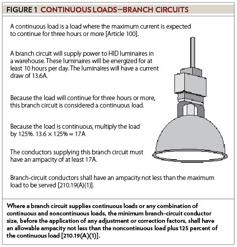
Because the term “continuous load” is in more than one article in the NEC, the definition is in Article 100. It is a load where the maximum current is expected to continue for three hours or more.
Branch-Circuit Conductor Sizing for Continuous and Noncontinuous Loads
Continuous load provisions pertain to branch circuits, feeders and services. Where a branch circuit supplies continuous loads, the minimum branch-circuit conductor size, before the application of any adjustment or correction factors, shall have an allowable ampacity not less than 125 percent of the continuous load [210.19(A)(1)]. In other than dwellings, lighting loads are usually considered continuous. For example, a branch circuit will supply power to high-intensity discharge (HID) luminaires in a warehouse. These luminaires will be energized for at least 10 hours per day. The luminaires will have a current draw of 13.6 amperes (A). Because the load will continue for three hours or more, this branch circuit is considered a continuous load. Therefore, multiply the load by 125 percent (13.6 × 125% = 17). The conductors must have an ampacity of at least 17A (see Figure 1).
If a branch circuit supplies both continuous and noncontinuous loads, the minimum branch-circuit conductor size, before the application of any adjustment or correction factors, shall have an allowable ampacity not less than the noncontinuous load plus 125 percent of the continuous load [210.19(A)(1)].
Feeder Conductor Sizing Using Continuous and Noncontinuous Load Calculations
Continuous loads are also a factor when sizing feeder conductors. The minimum feeder-circuit conductor size, before the application of any adjustment or correction factors, shall have an allowable ampacity not less than the noncontinuous load plus 125 percent of the continuous load [215.2(A)(1)]. After performing a load calculation in accordance with Article 220, divide the loads into two categories: continuous and noncontinuous. This separation directly affects conductor sizing and prevents undersizing due to long-duration loads. Multiply the continuous loads by 125 percent, and add to that number the noncontinuous loads. For example, Article 220 was used to calculate the loads for a feeder in a commercial building. While the calculation results for the continuous loads were 92A, the results for the noncontinuous loads were 74A. Start by multiplying the continuous loads by 125 percent. The minimum ampacity for continuous loads is 115A (92 × 125% = 115). Now add to this number the noncontinuous loads (115 + 74 = 189). The minimum ampacity for these feeder conductors is 189A (see Figure 2).
![Figure 2: Continuous Loads - Feeds. The minimum feeder conductor size, before the application of any adjustment or correctional factors, shall have an allowable ampacity not less than the noncontinuous load plus 125% of the continuous load [215.2(A)(1)].](/images/default-source/articles/figure-241f03379-0b41-4e0c-a152-bbf788d6cdbe.jpg?sfvrsn=f65f4fe9_1)
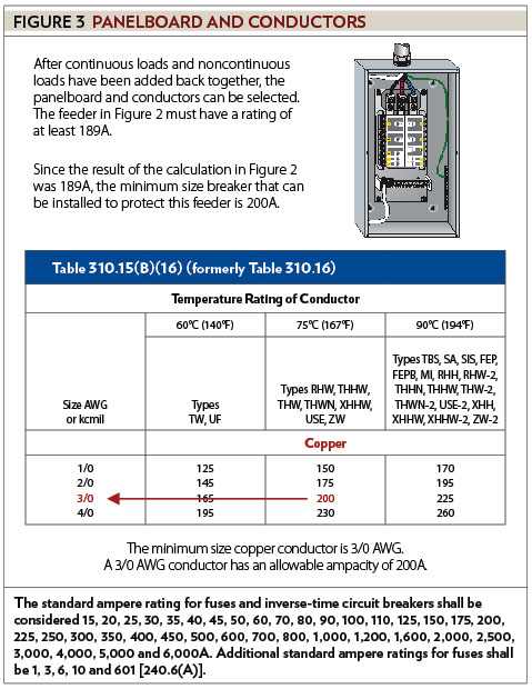
After continuous loads and noncontinuous loads have been added back together, the panelboard and conductors can be selected. The feeder in Figure 2 must have a rating of at least 189A. Standard ampere ratings for fuses and inverse-time circuit breakers can be found in 240.6(A). Since the result of the calculation in the last example was 189A, the minimum size breaker that can be installed for this feeder is 200A. In accordance with Table 310.15(B)(16), the minimum size 75°C (167°F) copper conductor is 3/0 AWG. A 3/0 AWG copper conductor has an allowable ampacity of 200A (see Figure 3).
Sizing Conductors for 200A Panelboards and Common Field Installations
Since the calculation result in Figure 2 was 189A, the conductor selected must have an ampacity of at least 189A. The minimum size 75°C (167°F) aluminum conductor is 250 kcmil. Aluminum conductors have lower ampacity per unit size than copper, requiring a larger conductor to achieve the same allowable ampacity rating. A 250 kcmil aluminum conductor has an allowable ampacity of 205A. In some installations, 4/0 AWG aluminum conductors are installed to supply a 200A panelboard. If the result of the calculation was 180A (or less) and the installation met the requirements in 240.4(B), it would be permissible to use 4/0 AWG aluminum conductors. A 4/0 aluminum conductor has an allowable ampacity of 180A. Remember, the ampacity of the conductor must not be less than the load.
Service-Entrance Conductor Sizing and Applying 125% Continuous Load Requirements
Like branch-circuit conductors and feeder conductors, service-entrance conductors have the same requirement for continuous loads. The ampacity of service-entrance conductors before the application of any adjustment or correction factors shall not be less than the sum of the noncontinuous loads plus 125 percent of continuous loads [230.42(A)]. For example, Article 220 was used to calculate the loads for a service at a retail store. While the calculation results for the continuous loads were 160A, the results for the noncontinuous loads were 165A. The minimum ampacity for continuous loads is 200A (160 × 125% = 200). Now add the noncontinuous loads to this number (200 + 165 = 365). The minimum ampacity for the service-entrance conductors is 365A. In accordance with 240.6(A), the next standard size rating above 365 is 400A. In accordance with Table 310.15(B)(16), the minimum size 75°C (167°F) copper conductor is 500 kcmil. A 500 kcmil copper conductor has an allowable ampacity of 380A. Since 380A is not a standard rating and the installation meets the provisions in 240.4(B), it is permitted to install 500 kcmil conductors on a 400A service (see Figure 4).
![Figure 4: Continuous Loads - Services. The ampacity of service entrance conductors before the application of any adjustment or correction factors shall not be less than the sum of the noncontinous load plus 125% of continuous loads [230.42(A)].](/images/default-source/articles/cif-0811_figure-4.jpg?sfvrsn=68128ba1_1)
There is a stipulation for all three conductor types pertaining to the use of an overcurrent device listed for operation at 100 percent of its rating. If the assembly, including the overcurrent devices protecting the conductors (branch-circuit, feeder or service), is listed for operation at 100 percent of its rating, the allowable ampacity of the conductors shall be permitted to be not less than the sum of the continuous load plus the noncontinuous load [210.19(A)(1) Exception, 215.2(A)(1) Exception No. 1, and 230.42(A)(2)]. This means that, if the overcurrent device is listed for operation at 100 percent of its rating, it is not necessary to multiply continuous loads by 125 percent.
There is an exception that applies to feeder conductors and service-entrance conductors; this exception pertains to grounded conductors. Grounded conductors that are not connected to an overcurrent device shall be permitted to be sized at 100 percent of the continuous and noncontinuous load [215.2(A)(1) Exception No. 2 and 230.42(A)(1) Exception]. As long as the grounded conductor is not connected to an overcurrent device, it is not necessary to multiply continuous loads by 125 percent.
Next month’s column will continue the discussion of sizing conductors.
About The Author
Charles R. Miller, owner of Lighthouse Educational Services, teaches custom-tailored seminars on the National Electrical Code and NFPA 70E. He is the author of “Illustrated Guide to the National Electrical Code” and “Electrician's Exam Prep Manual.” He can be reached at 615.333.3336 and [email protected]. Connect with him on LinkedIn.


