You're reading an older article from ELECTRICAL CONTRACTOR. Some content, such as code-related information, may be outdated. Visit our homepage to view the most up-to-date articles.
Sizing conductors is not a difficult task, but more is involved than referencing just one section, one article or even one chapter in the National Electrical Code (NEC). To select the correct conductor size, it is necessary to reference several sections throughout the Code. Before referencing the NEC, certain information is needed. Gather it by answering some key questions.
What is the lowest temperature rating of any connected termination, conductor or device? What is the connected load, or what is the calculated load in accordance with Article 220? Is the load or any part of the load continuous? What will be the maximum ambient temperature? How many current-carrying conductors will be in the raceway or cable? Will the conductors fall under the small-conductor rules in 240.4(D)? Will the conductors be feeder taps or transformer secondary conductors? Will the conductors supply any motors?
In the first two parts of this series, I covered termination temperature limitations; the third part covered continuous loads. Requirements for termination temperature limitations are in 110.14(C). Continuous load requirements are in 210.19(A)(1), 215.2(A)(1) and 230.42(A).
Conductors that supply continuous loads must also be sized to comply with the termination temperature provisions in 110.14(C). For example, a branch circuit will be installed in a nondwelling occupancy to supply power to a 16-ampere (A) continuous load. The circuit will be supplied from an existing 20A circuit breaker, and the temperature rating is not marked on the breaker. What is the minimum size THHN copper conductor required to supply power to this branch circuit?
Because this branch circuit load is a continuous load, multiply the load by 125 percent [210.19(A)(1)]. The conductors must have an ampacity of at least 20A (16 125% = 20). Table 310.15(B)(16), formerly Table 310.16, provides allowable ampacities for insulated conductors. Although a THHN conductor has a temperature rating of 90°C, the ampacity must not exceed the ampacity in the 60°C column.
Section 110.14(C)(1)(a) covers circuits rated 100A or less or marked for 14 AWG through 1 AWG conductors. While it is permissible to install a conductor with a higher temperature rating, the ampacity shall not exceed the 60°C ampacity of the conductor size used [110.14(C)(1)(a)(2)]. If any termination is either 60°C or unknown, the conductor’s maximum ampacity is listed in the 60°C column, regardless of the insulation rating of the conductor. The ampacity of a 12 AWG conductor in the 60°C column is 20A. Conductors supplying power to this branch circuit must be at least 12 AWG (see Figure 1).
It is not necessary to use the ampacity from the 60°C column if the equipment is listed and identified for use with such conductors [110.14(C)(1)(a)(3)]. This means the ampacity of a 75°C (or a 90°C) conductor can be based on the 75°C column if all the terminations are rated at least 75°C. For example, a 208-volt (V), single-phase branch circuit will be installed in a nondwelling occupancy to supply power to a 40A continuous load. The two-pole circuit breaker has a temperature rating of 75°C, and the termination on the other end also has a rating of 75°C. What are the minimum size THHN copper conductors required to supply power to this branch circuit? Because this branch circuit load is a continuous load, multiply the load by 125 percent [210.19(A)(1)]. The conductors must have an ampacity of at least 50A (40 125% = 50). Because all of the connection points in this example have at least a 75°C rating, the conductor’s ampacity can be based on the 75°C column. The ampacity of an 8 AWG conductor in the 75°C column is 50A. Conductors supplying power to this branch circuit must be at least 8 AWG (see Figure 2).
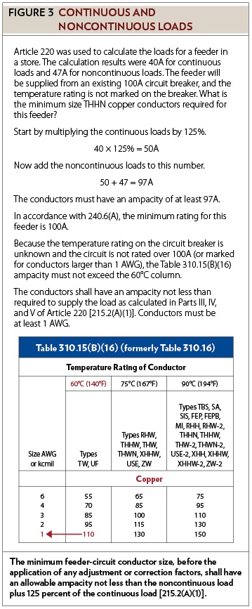
While one branch circuit could supply both continuous and noncontinuous loads, the combination of loads is more often found in feeders and services. The minimum feeder-circuit conductor size, before the application of any adjustment or correction factors, shall have an allowable ampacity not less than the noncontinuous load plus 125 percent of the continuous load [215.2(A)(1)]. After calculating the minimum ampacity, select a conductor from Table 310.15(B)(16). The conductor selected must not exceed the termination temperature provisions in 110.14(C). For example, Article 220 was used to calculate the loads for a feeder in a store. The calculation results for the continuous loads were 40A, and the results for the noncontinuous loads were 47A. The feeder will be supplied from an existing 100A circuit breaker and the temperature rating is not marked on the breaker. What are the minimum size THHN copper conductors required for this feeder? Start by multiplying the continuous loads by 125 percent. The minimum ampacity for continuous loads is 50A (40 125% = 50). Now add to this number the noncontinuous loads (50 + 47 = 97). The conductors must have an ampacity of at least 97A. In accordance with 240.6(A), the minimum rating for this feeder is 100A. Because the temperature rating on the circuit breaker is unknown and the circuit is not rated over 100A (or marked for conductors larger than 1 AWG), the Table 310.15(B)(16) ampacity must not exceed the 60°C column. The ampacity of a 2 AWG conductor in the 60°C column is only 95A, which is less than the calculated load. In the 60°C column of Table 310.15(B)(16), a 1 AWG conductor has an allowable ampacity of 110A. Conductors supplying power to this feeder must be at least 1 AWG (see Figure 3).
Requirements for service-entrance conductors are similar to the requirements for branch circuits and feeders. The ampacity of service-entrance conductors before the application of any adjustment or correction factors shall not be less than the sum of the noncontinuous loads plus 125 percent of continuous loads [230.42(A)]. For example, Article 220 was used to calculate the loads for a service in a store. The calculation results for the continuous loads were 88A, and the results for the noncontinuous loads were 130A. All the terminations will have a temperature rating of 75°C. What is the minimum size THHN copper conductor required for these service-entrance conductors? The minimum ampacity for continuous loads is 110A (88 125% = 110). Now add the noncontinuous loads to this number (110 + 130 = 240). The conductors must have an ampacity of at least 240A. In accordance with 240.6(A), the minimum rating for this service is 250A. Because of 110.14(C)(1)(b), the Table 310.15(B)(16) ampacity must not exceed the 75°C column. At times, it is permissible to install 4/0 AWG conductors on a 250A service but not in this example. The allowable ampacity of 4/0 AWG conductors is less than the calculated load. In the 75°C column of Table 310.15(B)(16), a 250 kcmil conductor has an allowable ampacity of 255A. Conductors supplying power to this service must be at least 250 kcmil (see Figure 4).
If any of the conductors in the previous examples were connected to overcurrent devices listed for operation at 100 percent of its rating, multiplying the continuous loads by 125 percent would not have been necessary: for branch circuits, see 210.19(A)(1) Exception; for feeders, see 215.2(A)(1) Exception No. 1; and for service-entrance conductors, see 230.42(A)(2).
This discussion will continue next month.
MILLER, owner of Lighthouse Educational Services, teaches classes and seminars on the electrical industry. He is the author of “Illustrated Guide to the National Electrical Code” and “The Electrician’s Exam Prep Manual.” He can be reached at 615.333.3336, [email protected] and www.charlesRmiller.com.
About The Author
Charles R. Miller, owner of Lighthouse Educational Services, teaches custom-tailored seminars on the National Electrical Code and NFPA 70E. He is the author of “Illustrated Guide to the National Electrical Code” and “Electrician's Exam Prep Manual.” He can be reached at 615.333.3336 and [email protected]. Connect with him on LinkedIn.


