You're reading an older article from ELECTRICAL CONTRACTOR. Some content, such as code-related information, may be outdated. Visit our homepage to view the most up-to-date articles.
Key Questions Before Selecting a Conductor
Selecting the correct size conductor involves referencing more than one section and more than one chapter in the National Electrical Code (NEC). The following questions must be answered before selecting conductors. What is the lowest temperature rating of any connected termination, conductor or device? What is the connected load, or what is the calculated load in accordance with Article 220? Is the load or any part of the load a continuous load? What will be the maximum ambient temperature? How many current-carrying conductors will be in the raceway or cable?
Understanding NEC Table 310.15(B)(16)
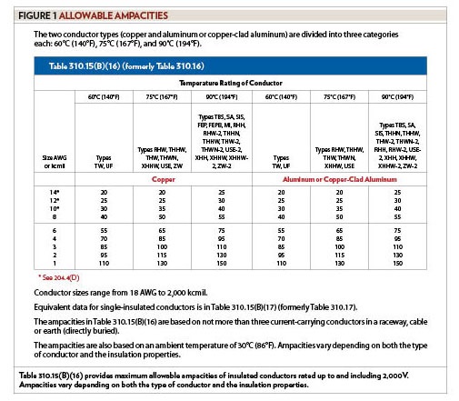
Table 310.15(B)(16) provides maximum allowable ampacities of insulated conductors rated up to and including 2,000 volts (V). (Before the 2011 edition of the Code, this table was Table 310.16). Table 310.15(B)(16) provides columns for copper and aluminum conductors. Ampacities for copper-clad aluminum conductors are in the same columns as aluminum conductors. The two conductor types are each divided into three categories: 60°C (140°F), 75°C (167°F) and 90°C (194°F). Conductor sizes range from 18 AWG to 2,000 kcmil. Equivalent data for single-insulated conductors is found in Table 310.15(B)(17) (formerly Table 310.17). The ampacities in Table 310.15(B)(16) are based on not more than three current-carrying conductors in a raceway, cable or earth (directly buried). The ampacities are also based on an ambient temperature of 30°C (86°F). Ampacities vary depending on both the type of conductor and the insulation properties (see Figure 1).
Conductor Ampacity Based on Temperature Ratings
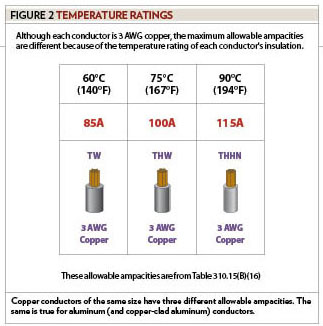
Copper conductors of the same size have three different allowable ampacities. The same is true for aluminum (and copper-clad aluminum) conductors. The maximum allowable ampacities depend on the conductor’s temperature rating. For example, a 3 AWG copper conductor with a temperature rating of 60°C has a maximum allowable ampacity of 85 amperes (A). The maximum allowable ampacity of the same 3 AWG copper conductor with a temperature rating of 75°C is 100A. If the temperature rating of the 3 AWG copper conductor is 90°C, the allowable ampacity is 115A (see Figure 2).
Conductor Construction and Insulation Ratings
Table 310.104(A) contains information about conductors rated 600V. Before the 2011 edition of the Code, this table was Table 310.13(A). Conductor information in this table includes trade name, type letter, maximum operating temperature, application provisions, insulation, thickness of insulation, and outer covering (if any). Conductor application and insulation for conductors rated higher than 600V are in Tables 310.13(B) through (E).
Coordinating Termination Ratings and Conductor Ampacity
Type THHN building wire is a common conductor used throughout the construction industry. This conductor has a maximum operating temperature rating of 90°C. Just because a conductor has insulation with a 90°C temperature rating, the ampacity is not automatically selected from the 90°C column. Instead, the appropriate column for conductor ampacity selection depends on the temperature rating of the termination (or connection) points. In accordance with 110.14(C), the temperature rating associated with a conductor’s ampacity shall be selected and coordinated so that the lowest temperature rating of any connected termination, conductor or device is not exceeded. Electrical workers should always verify the manufacturer’s temperature rating on equipment label plates and enclosures before assuming terminal compatibility. The determination of termination provisions of equipment shall be based on 110.14(C)(1)(a) or (C)(1)(b). While 110.14(C)(1)(a) covers circuits rated 100A or less or marked for 14 AWG through 1 AWG conductors, 110.14(C)(1)(b) covers circuits rated over 100A or marked for conductors larger than 1 AWG.
NEC 110.14(C): Termination Provisions
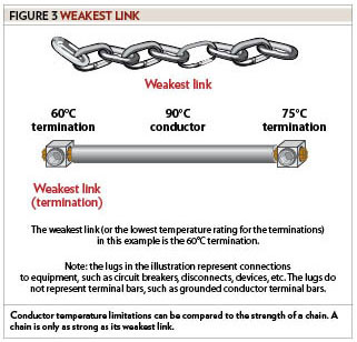
Unless the equipment is listed and marked otherwise, conductor ampacities used in determining equipment termination provisions shall be based on Table 310.15(B)(16) as appropriately modified by 310.15(B)(7). A conductor has at least two ends or terminations. Each termination has a temperature rating. If at least one temperature rating is unknown, use the default ratings in 110.14(C)(1)(a) or (C)(1)(b). This ensures NEC compliance and avoids potential overheating at weaker termination points. Conductor temperature limitations can be compared to the strength of a chain. A chain is only as strong as its weakest link. For example, a 90°C conductor has a 60°C termination on one end and a 75°C termination on the other. The weakest link in this example is the 60°C termination (see Figure 3).
Circuits rated 100A or less
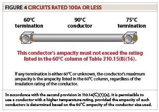
There are four provisions for circuits rated 100A or less or marked for 14 AWG through 1 AWG conductors. The conductor selection must be based on one of these four provisions. The first provision instructs us to use a conductor rated 60°C. The maximum ampacity for a 60°C conductor is listed in the 60°C column of Table 310.15(B)(16). The first provision is very limited because the only conductors with a 60°C temperature rating are Types TW and UF. Type machine tool wiring (MTW) in a wet location also has a 60°C rating. In accordance with the second provision in 110.14(C)(1)(a), it is permissible to use a conductor with a higher temperature rating, provided the ampacity of such conductors is determined based on the 60°C ampacity of the conductor size used. If any termination is either 60°C or unknown, the conductor’s maximum ampacity is the ampacity listed in the 60°C column, regardless of the insulation rating of the conductor. For example, a THHN conductor will have a 60°C termination on one end and a 75°C termination on the other. Despite the conductor’s higher insulation rating, the ampacity must be limited by the lowest-rated connection point. Because one of the connection points has a 60°C rating, the conductor’s ampacity must not exceed the rating listed in the 60°C column (see Figure 4).
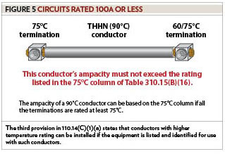
The third provision in 110.14(C)(1)(a) states that conductors with higher temperature ratings can be installed if the equipment is listed and identified for use with such conductors. This means the ampacity of a 75°C conductor can be based on the 75°C column if all the terminations are rated at least 75°C. This also means the ampacity of a 90°C conductor can be based on the 90°C column if all the terminations are rated at least 90°C. Be careful when using the 90°C column because no equipment is listed and identified for use with 90°C conductors other than individual lugs, terminal bars and equipment listed for use on circuits over 600V. This third provision in 110.14(C)(1)(a) also means the ampacity of a 90°C conductor can be based on the 75°C column if all the terminations are rated at least 75°C. For example, a THHN conductor will have 75°C termination on one end and a 60/75°C termination on the other. A temperature rating of 60/75°C means the equipment has been listed for both 60°C and 75°C conductors; therefore, it is permissible to use the 75°C rating if the installed conductor is rated at least 75°C. Because all of the connection points in this example have at least a 75°C rating, the conductor’s ampacity can be based on the 75°C column (see Figure 5).
Next month’s Code in Focus continues the discussion of termination temperature limitations.
About The Author
Charles R. Miller, owner of Lighthouse Educational Services, teaches custom-tailored seminars on the National Electrical Code and NFPA 70E. He is the author of “Illustrated Guide to the National Electrical Code” and “Electrician's Exam Prep Manual.” He can be reached at 615.333.3336 and [email protected]. Connect with him on LinkedIn.