
You're reading an older article from ELECTRICAL CONTRACTOR. Some content, such as code-related information, may be outdated. Visit our homepage to view the most up-to-date articles.
ARTICLE 314 C OUTLET, DEVICE, PULL AND JUNCTION BOXES; CONDUIT BODIES; FITTINGS; AND MANHOLES
Overview of NEC 314.16 Box-Fill Requirements
Calculating Box Volume and Conductor Fill Per NEC 314.16(B)
Requirements pertaining to the installation and use of all boxes and conduit bodies used as outlet, device, junction or pull boxes are in Article 314 of the National Electrical Code. Procedures for calculating maximum numbers and sizes of conductors (6 AWG and smaller) are in 314.16. Box-volume calculations are in 314.16(A), box-fill calculations are in 314.16(B), and requirements pertaining to conduit bodies enclosing 6 AWG conductors or smaller are in 314.16(C). Last month's Code In Focus concluded with 314.16(B)(1). This month, the discussion continues with box-fill calculations.
The volume allowances required per conductor sizes 18 AWG through 6 AWG are listed in Table 314.16(B). These values ensure electrical contractors size boxes correctly to maintain adequate free space and prevent overheating or insulation damage. The free space required for each conductor is given in cubic centimeters and cubic inches. The volume allowances range from 1.5 cubic inches (24.6 cubic centimeters) for 18 AWG conductors to 5 cubic inches (81.9 cubic centimeters) for 6 AWG conductors (see Figure 1). The volume of the box, as calculated in 314.16(A), must not be less than the fill calculation as calculated in 314.16(B). This protects conductor insulation from compression, which could lead to abrasion, overheating or code violations during inspections.
Applying Volume Allowances for Mixed Conductor Sizes
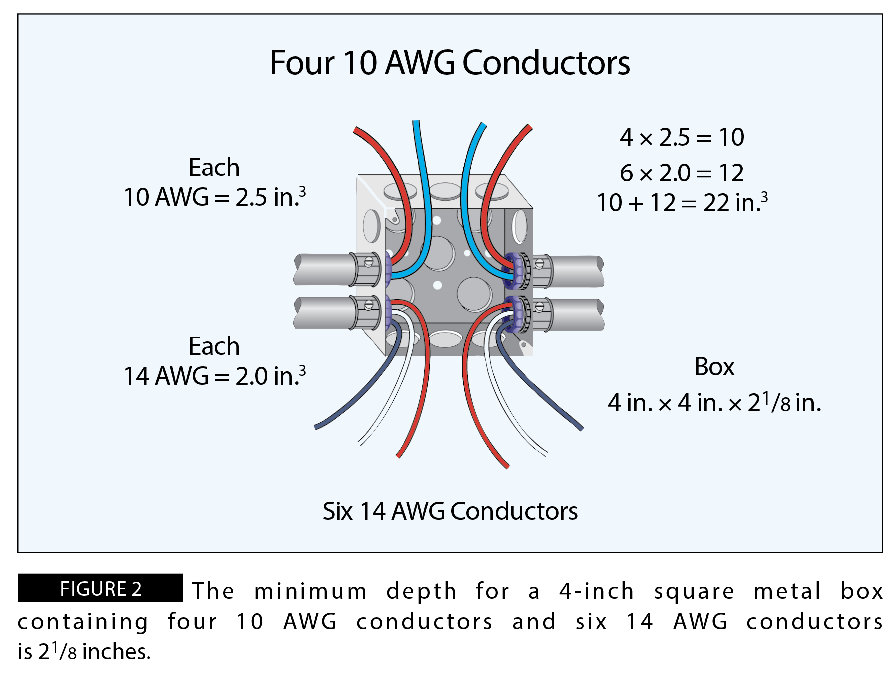
When the box contains different size conductors, or the box is not listed in Table 314.16(A), a volume calculation must be performed. Mixed conductor sizes require calculating based on each size’s individual volume allowance to ensure that all conductors have the proper free space within the enclosure. For example, a box is needed for four 10 AWG conductors and six 14 AWG conductors, so what would be the minimum depth 4-inch square metal box that can be installed? The box will not contain any fittings of devices. To figure this out, first calculate the volume required for each set of conductors. The volume required for each 10 AWG conductor is 2.5 cubic inches. Therefore, the volume required for the 10 AWG conductors is 10 cubic inches (4 2.5). Since the volume required for each 14 AWG conductor is 2 cubic inches, the volume needed is 12 cubic inches (6 2). The total volume required for four 10 AWG conductors and six 14 AWG conductors is 22 cubic inches (10 + 12). The minimum depth 4-inch square metal box is 2 1/8 inches (see Figure 2).
Determining Additional Conductor Space for Existing Boxes
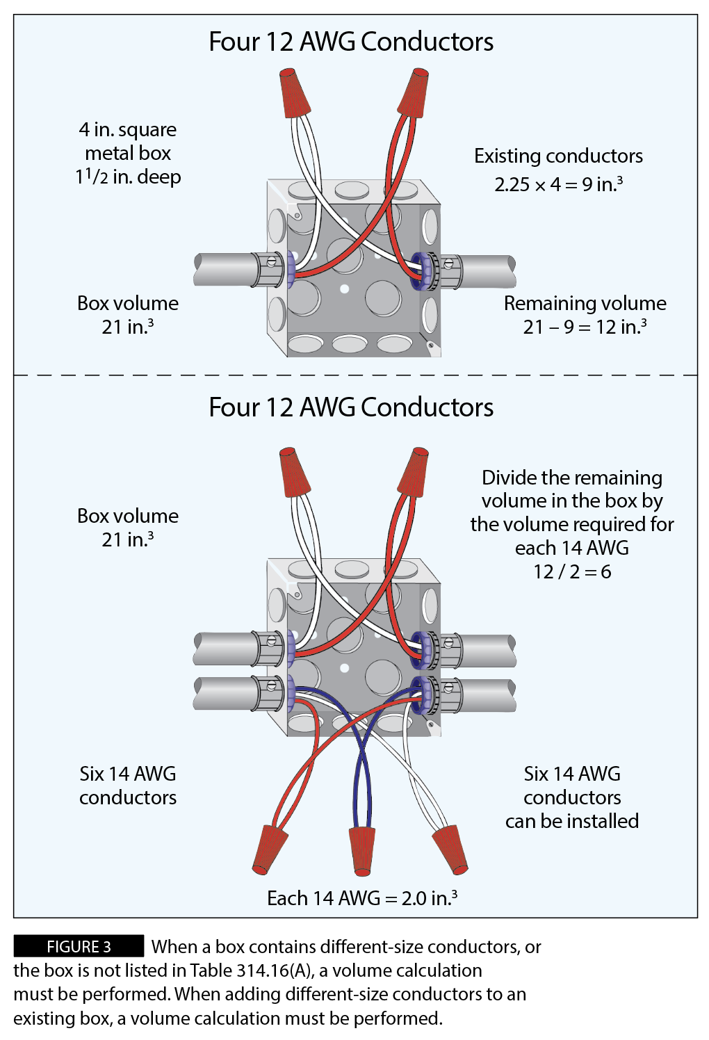
Occasionally, boxes are already installed and additional conductors must be added. Reevaluating the box-fill ensures electricians avoid overfilling existing boxes, which is a common source of NEC violations during renovations or service upgrades.
If the new conductors are the same size as the existing conductors, find the maximum number in Table 314.16(A). If the new conductors are not the same size as the existing conductors, a volume calculation must be performed. For example, a 4-inch square metal box with a depth of 11/2 inches currently contains four 12 AWG conductors. How many 14 AWG conductors can be added? The box contains no fittings or devices. The first step is to find the cubic-inch capacity of the box from Table 314.16(A). A 4-inch square box that is 11/2 inches deep has a volume of 21.0 cubic inches. Next, calculate the volume for the existing conductors. The volume required for each 12 AWG conductor is 2.25 cubic inches, and therefore the volume required for four 12 AWG conductors is 9 cubic inches (4 2.25). Next, deduct the volume of the existing conductors from the volume of the box. The space remaining in the box is 12 cubic inches (21 - 9). As per Table 314.16(B), the minimum volume allowance for each 14 AWG conductor is 2.0 cubic inches. Finally, divide the available space in the box by the cubic-inch volume for each 14 AWG. Six 14 AWG conductors can be installed to this box (12 / 2 = 6) (see Figure 3).
Up to now, no consideration was given to fittings, devices or equipment-grounding conductors in the box-fill calculations. Specifications for clamp fill, support fittings fill, device or equipment fill, and equipment-grounding conductor fill are in 314.16(B)(2) through (5). Since most boxes contain more than just conductor and wire connectors, it is important to have a good understanding of which items are counted and how much volume is required for those items.
Clamp Fill Requirements under NEC 314.16(B)(2)
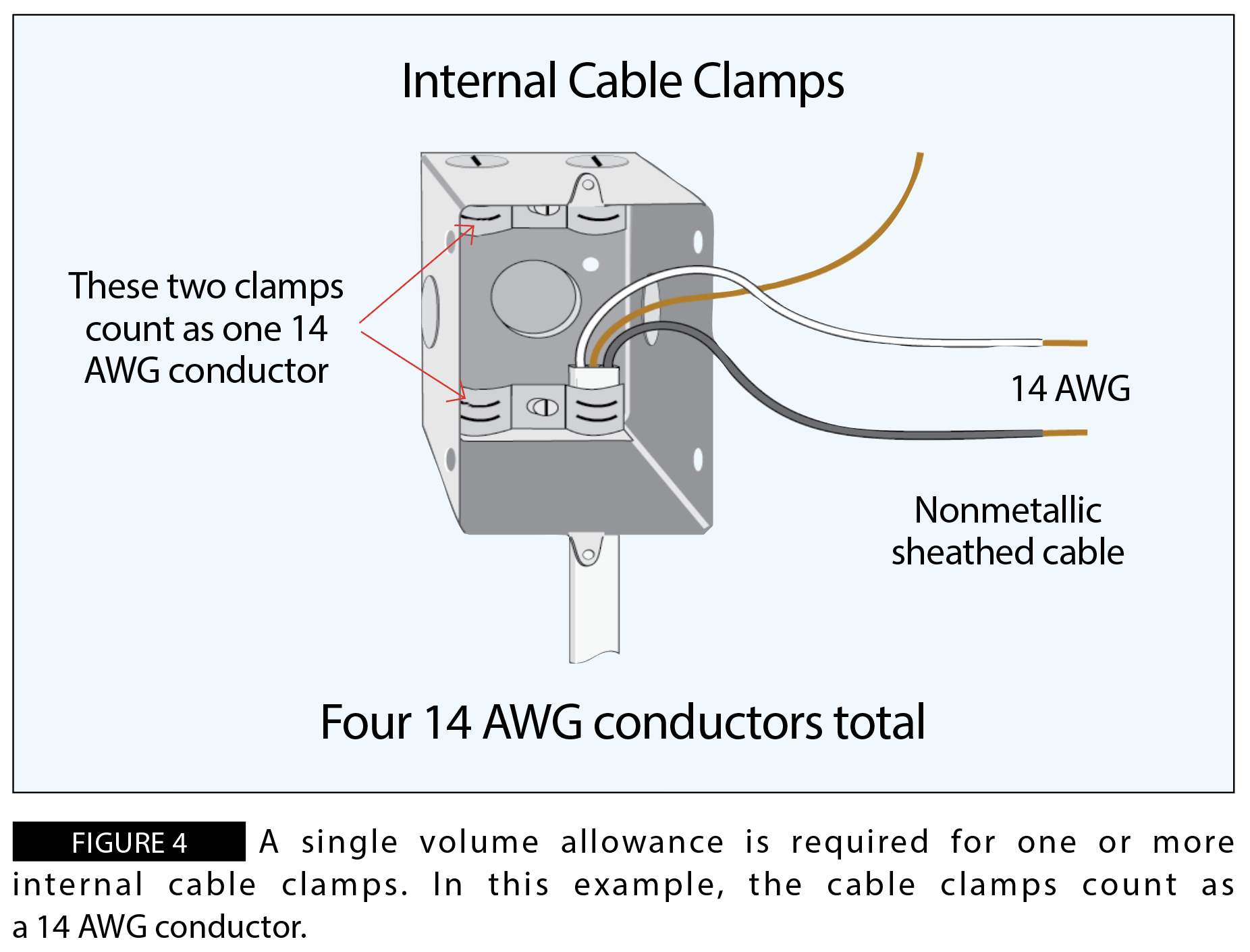
Where one or more internal cable clamps, whether factory or field supplied, are present in the box, a single volume allowance in accordance with Table 314.16(B) shall be made based on the largest conductor present in the box. This means that one or more internal cable clamps are counted as one conductor. If one size conductor is in the box, the cable clamp(s) counts as one of those conductors. For example, a metal device box is equipped with two internal cable clamps. One 14-2 with ground nonmetallic sheathed cable is installed in the box. Although there are two cable clamps, they only count as one conductor. Instead of the box containing three 14 AWG conductors, four 14 AWG conductors must be counted (see Figure 4).
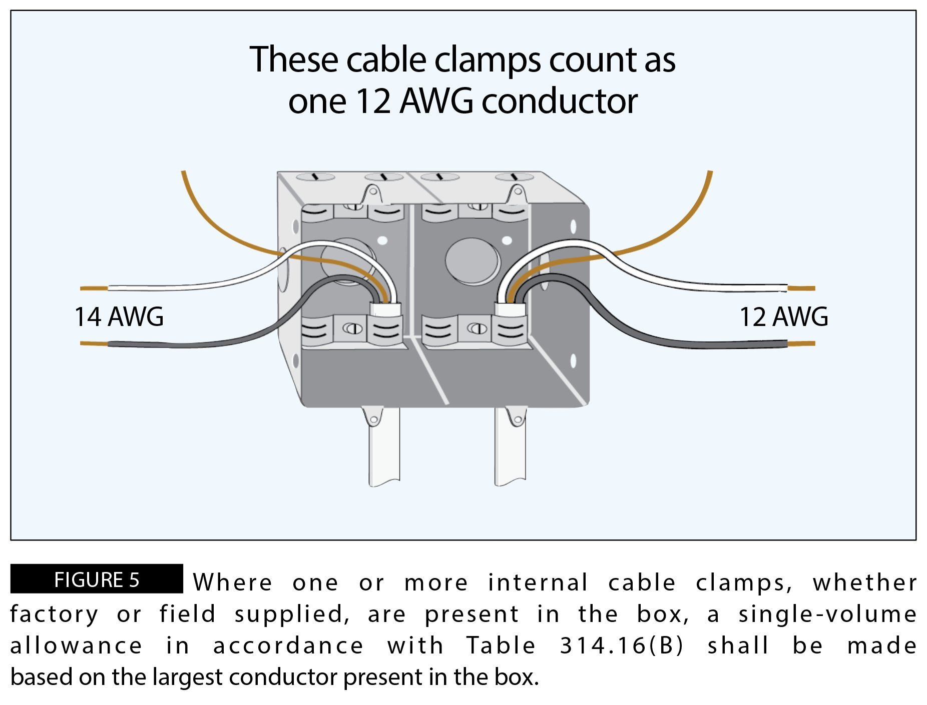
If the box contains more than one-size conductor, the internal cable clamps must be counted as one of the largest-size conductors that are in the box. This prevents under sizing the box when larger conductors consume more physical space, helping maintain compliance with NEC 314.16(B)(2). For example, a two-gang metal device box is equipped with four internal cable clamps. One 14-2 with ground nonmetallic sheathed cable and one 12-2 with ground nonmetallic sheathed cable are installed in the box. Because there are different-size conductors in the box, the clamp counts as one 12 AWG conductor (see Figure 5).
Internal vs. External Clamps and Their Impact on Box-Fill Calculations
No allowance is required for a cable connector with its clamping mechanism outside the box. Because the clamp mechanism does not occupy internal box volume, it does not reduce available space for conductors, fittings or devices. Cable connectors, configured so that the clamping mechanism falls outside the box, are not counted and therefore no volume allowance is required. For example, a cable connector has been installed on each end of a metal device box. The cable connector's clamping mechanism is located on the outside of the box. Since the clamping mechanism falls outside the box, these clamps are not counted as conductor fill (see Figure 6). These clamp-fill provisions are applicable whether the cable is nonmetallic or metallic.
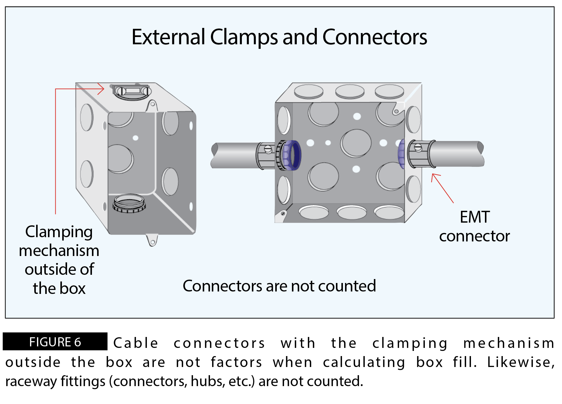
While internal clamps for cables such as Type AC and Type MC are counted, if the clamping mechanism is outside the box, they are not counted. External connectors for conduit and tubing (EMT, PVC, ENT, FMC, etc.) are also not counted in box-fill calculations and, as previously mentioned, locknuts and bushings are not counted. Next month's Code In Focus continues the discussion of box-fill calculations.
<< Read Part V | Read Part VII >>
About The Author
Charles R. Miller, owner of Lighthouse Educational Services, teaches custom-tailored seminars on the National Electrical Code and NFPA 70E. He is the author of “Illustrated Guide to the National Electrical Code” and “Electrician's Exam Prep Manual.” He can be reached at 615.333.3336 and [email protected]. Connect with him on LinkedIn.


