You're reading an older article from ELECTRICAL CONTRACTOR. Some content, such as code-related information, may be outdated. Visit our homepage to view the most up-to-date articles.
It is difficult to imagine wiring a large commercial project without using an electrically powered cable puller.
Available in different sizes with pulling forces between 1,000 and 10,000 pounds, electrically powered pullers and accessories make cable installation easier, faster and more efficient.
Basic components of most power-pulling tools include frame, power source, the capstan that pulls the pulling rope and wire, and the mechanism that turns the capstan and pulling rope. Product differences are found in how their designs employ these components.
Frequently used pulling accessories include cable feeders, support and feeding sheaves, pulling grips, force gauges, remote foot controls, and pulling lubricants.
The focus of this report is on pulling electrical power cables. While some installers may use the same pulling equipment for datacom work, low-voltage cable and especially fiber optic cable must be handled differently than power cable.
Electric pulling equipment should be used for any pull that requires forces greater than 300 pounds, according to Ibrahim El-Natour, associate product manager for pulling and fishing, Greenlee. Greenlee offers electromechanical pullers, mechanical pullers, power fishing systems, and power utility pullers and tensioners.
Greenlee has introduced three new pulling products in the past 24 months: a 2,000-pound, one-piece model; a 10,000-pound ultra tugger with a quick setup boom; and a vacuum blower used in the prepulling stage.
“Selecting the correct rope is essential to the pull,” El-Natour said. “The rated capacity, rather than the average breaking strength, must always be considered when selecting pulling rope. Greenlee pulling rope is double-braided, composite rope.
“At the feeding end, an electric cable feeder greatly reduces the effort required to feed cables into the conduit or tray.
“Lubricants should be used whenever possible and are available in gel, cream and liquid varieties and should be used in accordance with wire and cable manufacturers’ recommendations.
“Cable pulls, especially those requiring large forces, can be extremely dangerous. Always follow specific product instruction manuals and standard safe practices when pulling cable,” El-Natour said.
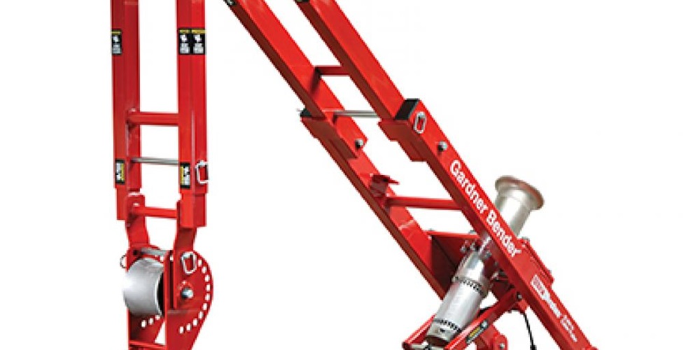
Dan Smelter, senior product manager, Gardner Bender, said that two-speed power cable pullers have become increasingly popular because one machine can provide both high and low pulling-load capabilities.
“Gardner Bender offers an 8,000-pound puller with 25 pulling configurations and a 10,000-pound model, providing exceptional mobility and rapid setup and teardown,” Smelter said. “All our cable pullers have a nonreversing planetary gear motor for smooth, consistent pulling.
“Power fishing systems are used to blow the initial pull line and/or conduit measuring tape via a line carrier through the raceway with forced air. Conventional systems are based on 115V [volt] blower/vacuum systems. We offer an innovative power fishing system powered by carbon dioxide, which can be operated when electrical power is not available,” Smelter said.
Don Godfrey, product manager, Southwire, said manual or hand pulls should be a thing of the past.
“With the many lightweight puller models in the industry today combined with advances to other materials, such as no-lube wire and improved pulling ropes for lower coefficient of friction, pulls can be set up quickly and pulled at faster speeds, providing higher levels of safety and more productivity,” he said.
“Southwire offers three Maxis high-speed cable pullers in ratings of 3,000, 6,000 and 10,000 pounds.
“A pivoting arm has been added to our 10,000-pound cable puller for easy rope access in overhead pulling applications as well as solid rubber puncture-proof tires.
“The 3,000-pound model is a lightweight, high-speed puller and provides a safe, portable and more efficient alternative to traditional methods of pulling wire. It is fast and easy to set up and is used on small and mid-sized runs. Dual remote foot switches that control the power source are available for all Maxis models and are operative from either end of a pull.
“Our new smart tensiometer measures pulling variables and wirelessly streams information to smartphones or tablets,” he said (see sidebar on page 104).
“Southwire offers an innovative, new, high-performance pulling rope that is UV-resistant, lightweight and ultra-low stretch for all your feeder and circuit wire solutions. A 12-strand single braided 9/16-inch diameter rope has a breaking strength of 32,000 pounds. It does not absorb water and has shown to reduce the coefficient of friction by approximately 24 percent compared to traditional pulling rope,” Godfrey said.
[SB]Many factors influence puller choice. According to El-Natour, it is important to understand how pulling force affects a pulling installation when selecting equipment.
“Force is the amount of energy needed to pull cable through conduit,” he said. “It is dependent on multiple factors. The total force required is not constant throughout the pull. Typically, force builds as the pull progresses. This means that for most pulls, the final stages are when the maximum force is being applied to the equipment. This is when pull failures are most likely to occur. That’s why it is important to select the right equipment for the job. Too small, a puller gets the pull started but may not be able to finish it, resulting in downtime and increased job costs. More importantly, using rope, cables or equipment at forces higher than their rated capacities is dangerous and can cause sheaves or rope to break.
“Think of pulling cable like stretching a rubber band. As it is pulled, the energy applied is stored inside the band. Apply too much force for a rope’s rating, and it can snap, releasing the stored energy. When this happens, it may damage conduit, pullers can be damaged, and anyone who happens to be in the way of the cable can be injured.
“Calculating the force necessary to make a pull involves the number and weight of cables, distance of the conduit run, the vertical and horizontal sections of the conduit, and direction of changes such as elbows and stubs. Increasing any of these variables will increase the total force required to make the cable pull. By combining these values, an estimate can be made for the total force required for the pull, and equipment can be selected accordingly.
“Obviously, as the weight of cables and number of cables increase, so does the force necessary to pull it. To determine weight, it is necessary to know the per-foot weight of cable or cables to be installed.
“When calculating force, a run should be divided into sections of vertical and horizontal paths. Directional changes must be considered. Pulls or ‘legs’ that move upward from floor to floor (vertical runs) will require much higher forces than those that move from room to room (horizontal runs) because the weight of the cable must be lifted as it passes through the conduit.
“Pulling cable down from floor to floor requires much less force because the cable will be able to ‘drop’ through the conduit by its own weight. It is still necessary to calculate force required for the drop, but the figure produced will be a negative number and is subtracted from the total force calculation,” El-Natour said.
“A word of caution about vertical pulls. Because less force is needed, it may be tempting to always pull from the top down. However, this can create a situation where the weight of the cable can run away through the conduit when the weight of the cable overcomes the ability of the pulling equipment to restrain its speed. This can occur faster than a person can get out of the way and result in injury or worse. Therefore, runs with long vertical sections should always be performed with the puller on the higher level and the feeder below.
“To calculate necessary force for horizontal sections, it is necessary to know the coefficient or drag friction. For many common wire types, the coefficient of friction is 0.38. Cable manufacturers’ specifications provide specific figures. A cable lubricant can lower the coefficient of friction 0.1 or 0.2, depending on the type of lubricant.
“Generally, the longer the conduit run, the more force is required for the pull. As previously discussed, conduit runs with long downward sections may be exceptions since the cable is free to drop through the conduit with very little pulling required.
“Most direction changes increase the force required to pull cable by about 1.4 times for every 90 degree elbow. For long, sweeping bends, this number will be lower. Do not use this figure if the elbow is at the end of the downward section, since the force required to navigate the bend are minimal.
“Changes in conduit direction are the largest contributors to increased force for cable pulls. Conduit runs should contain no more than 360 degrees of bends—in other words, no more than four 90-degree elbows—due to the force required to pull cable through it. With all information in hand, the required force for a pull is calculated with this formula: total cable weight times length of pull times coefficient of friction times number of direction changes. The calculation must be repeated for each segment of the pull,” El-Natour said.
Note: This discussion about calculating pulling force is for your information only. It is general and does not represent a specific pulling installation. Force calculations must be made for each pull and incorporate all variables, including any not cited in this summary. Those calculations might include, but are not limited to, increased force needed for pulls with bends in excess of 90 degrees or overfilling conduit with cable or cables.
About The Author

GRIFFIN, a construction journalist from Oklahoma City, can be reached at [email protected].