You're reading an older article from ELECTRICAL CONTRACTOR. Some content, such as code-related information, may be outdated. Visit our homepage to view the most up-to-date articles.
Careful documentation can help
Gone are the days when all fiber optic cables were the same. Most building cables had 62.5/125 micron multimode fibers for LANs or security systems, while outside plant cables were all single-mode fiber. For some time, we have been encouraging people to install hybrid cables with both multimode fibers for today and single-mode fibers for the future.
In the last few years, fiber manufacturers have been offering “laser-rated” multimode fibers (see related column in the June 2003 issue) that have a 50-micron core, smaller than the 62.5 micron core of fibers normally installed. The incompatibility of the core sizes has created a new set of problems for contractors and installers working on installations that have more than one type of fiber.
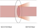
The problem is created by the different sizes of the light-carrying core of the fibers, just like different conduit or pipe sizes. All have the same cladding diameter (125 microns), so it’s hard to identify them and notice the differences when terminating or splicing them.
If you are transmitting from a smaller fiber core to a larger one, it is not a problem since the larger fiber will collect all the light from the smaller one with minimal loss. But if you transmit light from a larger fiber to a smaller one, the light in the larger core will overfill the smaller core and large losses will occur.
How big are the losses we are talking about? Coupling a multimode fiber to a single-mode fiber will cause about 20 dB loss. Connecting a 62.5 fiber to a 50 micron core fiber will cause 2 to 4 dB loss, depending on the type of source (laser or LED). In any case, it can be enough loss to prevent network equipment from working properly.
Sometimes the original installation used hybrid cables, but only the multimode fibers were terminated. The plan was to terminate the single-mode fibers when needed. We know of installations where the documentation was poor or nonexistent and neither the user nor the contractor hired to terminate the spare fibers realized they were single-mode. Terminating them in the field with multimode connectors and testing them with 62.5 micron patchcords created a panic—all the connectors looked fine on a microscope, but tested at about 20 dB loss!
A few panicked phone calls later, the installer looked at the connector ends again, but this time with a visual fiber tracer shining down the fiber. Then the tiny single-mode core made the problem obvious. But retesting with single-mode patchcords still showed high loss, a result of the poorer tolerances of the multimode connectors used to terminate the single-mode fibers and the rougher polish that is acceptable in multimode connectors but cannot be tolerated with single-mode fiber. All the connectors had to be cut off and reterminated, this time by fusion splicing factory-made pigtails onto the fibers.
We have heard from installers about similar problems with the two different multimode fibers. Both 50 micron and 62.5 micron multimode fibers have the same cladding diameter and can use the same connectors and termination processes, but testing still requires using the correct matching patchcords or the measured loss will be too low by a few tenths of a dB in one direction (50 to 62.5), or 2 to 4 dB too high the other way (62.5 to 50.)
Needless to say, these mismatched fiber losses affect the end user the same way they affect the installer, creating excess connection loss that can cause systems to malfunction or have high error rates, causing an expensive and annoying service call. Unfortunately, there is no optical mating adapter that will match two dissimilar fibers—although it has been tried many times. There is no solution other than preventing mismatched fiber terminations.
Of course, most fibers are marked with the fiber diameters on the jacket, but it’s often hard to read, especially in a poorly-lit telecomm room. You would think the standards-centric cabling industry would have specified color codes for cables containing each type of fiber, but it has not happened yet. Traditionally, an orange-jacketed cable means multimode and yellow means single-mode. In Europe and with the U.S. military, 50/125 is orange and 62.5/125 is gray. A new standard in process will have 50 or 62.5 fiber as orange but laser-rated 50-micron fiber as aqua. However, many cables are still produced in colors specific to customer orders.
The only method to prevent confusion is to document the fibers when terminated, label them and, if possible, choose connectors with color-coded boots. Stock color-coded and marked patch cables separately and put signs up noting their usage. And, of course, make sure everyone involved—both the installers and users—knows that there are incompatible fiber optic cables in the telecomm rooms affected. EC
HAYES is a VDV writer and trainer and the president of The Fiber Optic Association. Find him at www.JimHayes.com.
About The Author

HAYES is a VDV writer and educator and the president of the Fiber Optic Association. Find him at www.JimHayes.com.