You're reading an older article from ELECTRICAL CONTRACTOR. Some content, such as code-related information, may be outdated. Visit our homepage to view the most up-to-date articles.
While we’re on the subject of tools, we should look at some of the testing tools in a fiber optic toolbox that often do not get enough attention (see Fiber Optics, February 2013). We often instruct techs to use a power meter to test loss or measure the power at the transmitter or receiver for troubleshooting, but we usually assume they know how this gadget works and the proper way to use it.
A fiber optic power meter is just a fancy light meter designed to measure the light coming out of an optical fiber. A detector made from semiconductor materials converts the light to an electrical signal and then amplifies and measures it for display on a digital readout. Since that light is generally in the infrared, in the range of 850 to 1,550 nanometers (nm), special detectors are needed. Germanium (Ge) and indium gallium arsenide (InGaAs) are the two types of detectors in common usage, with Ge being less expensive and InGaAs being more sensitive. For systems that use only multimode fiber at 850 nm or plastic fiber at 650 nm, silicon detectors can be used.
All these detector types share a common trait: their sensitivity varies with the wavelength of light. Therefore, they must be calibrated at the wavelengths of interest traceable to international standards. Since 850, 1,300 and 1,550 nm are the common wavelengths of fiber optics, those are the wavelengths for which calibration standards are available. Some meters also are calibrated at other wavelengths used in some fiber optic systems like 1,490 or 1,625 nm. Some meters even have calibration at 1,300 nm and at 1,310 nm (the wavelength defined for lasers), but there is no real difference between the two wavelength calibrations.
Whenever you are making power or loss measurements, the power meter must be set at the wavelength of the source at the other end of the cable being tested, either the test source or system source.
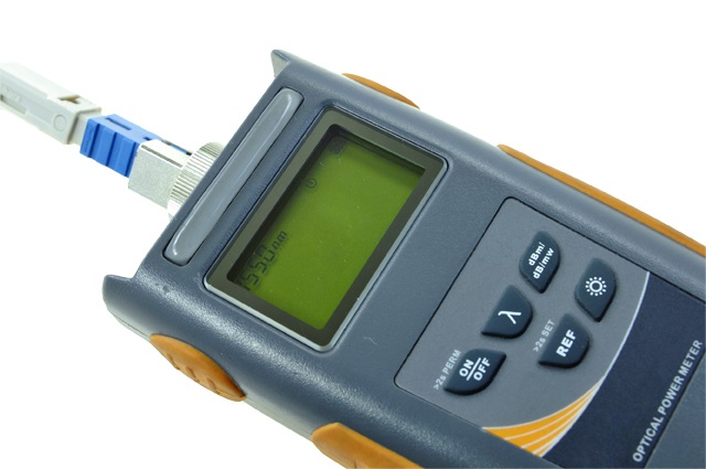
The end of the optical fiber being measured must be aligned with the detector in the power meter and held securely, usually by a removable adapter that allows changing to fit different styles of fiber optic connectors, e.g., SC, LC or ST. The detector must be large enough to capture all the light from the end of the fiber no matter what type of fiber or connector is being tested.
The connector adapter should be removed from the power meter occasionally to clean the adapter and the detector window. Be careful when doing this as the detector window is very thin to ensure high light transmission.
The measurement of the power meter is usually in decibels (dB), a logarithmic range that allows the meter to measure power over a range of up to 1 million to 1, sometimes necessary in fiber optic testing. There will be two dB scales: “dB” and “dBm.” dB is a relative measurement, the ratio of two power levels used for measuring loss, where you measure a 0-dB reference and then the dB loss. The meter will usually allow you to make a relative measurement and set an arbitrary 0-dB point for testing loss. dBm is a measurement of absolute power, relative to 1 milliwatt of power, and is used to measure the actual output of a source or the input of a receiver when testing system performance.
When measuring loss, always use the dB scale, so you can use the meter’s relative function to set a 0-dB reference for testing loss easily.
Fiber optic power meters do not require a lot of maintenance. Keep the detector and connector adapter clean, of course, but also keep the batteries charged or have replacements on-hand. Handle power meters carefully; they are delicate instruments.
Every couple of years, you need to have your meter calibrated. A calibration service will check out the operation completely, including the meter’s linearity—how well it conforms to calibration over the full operating range. Then, the servicers will calibrate it to the international transfer standards for fiber optic power, so it will measure the same power level as other meters, allowing correlation of tests by different users.
If you are doing work for government or military customers or any knowledgeable customer, you may be asked to submit a calibration certificate for your power meter and other test equipment; be sure it is calibrated on the proper schedule, and know where to find the calibration certificate when required by customers.
Like all the other tools in your toolbox, your fiber optic power meter requires understanding of how it works, how to use it and how to take proper care of it to get good service from your investment.
About The Author

HAYES is a VDV writer and educator and the president of the Fiber Optic Association. Find him at www.JimHayes.com.


