You're reading an older article from ELECTRICAL CONTRACTOR. Some content, such as code-related information, may be outdated. Visit our homepage to view the most up-to-date articles.
A certification tester is the basic instrument for certifying that a building’s structured wiring meets industry standards. At one time, structured wiring referred to a facility’s communications network, but that has changed. The continuing trend toward integrated systems incorporates surveillance, security and alarm, and building controls into structured wiring, and they should be certified to applicable standards.
Two primary suppliers of certification testers—Ideal Industries and Fluke Networks—discuss advances in certification testers and the extended applications for which they are used.
According to Dan Payerle, business unit manager for Ideal Networks, a division of Ideal Industries: “Integrated systems—such as paging, CCTV, HVAC, access control, telemetry, digital signage, etc.—fall into what the TIA [Telecommunications Industry Association] calls intelligent building systems.
“The standard that provides guidelines for all aspects of structured cabling for intelligent building systems is the TIA-862-B. The 862-B standard includes recommendations for cabling design that varies depending on the intended type of area being wired. For example, in parking lots, the standard recommends a communications circuit be installed to cover an area of 50 square meters [about 540 square feet], while in retail, office, hotel and other occupied spaces, there should be a circuit for every 25 square meters [about 270 square feet].
“For testing, the 862-B standard refers to the well-known TIA-568-C, which describes testing with certifiers. From the point of view of standards-writing organizations, cabling for intelligent building systems is not treated much differently than cabling for typical commercial buildings.
“It is important to remember that testing with certifiers is not a requirement of a standards-compliant structured cabling system. The standards recommend certification testing and define the very specific measurements that are performed by certification testers. Whether the cabling is tested with a certifier, transmission tester or qualifier is a decision the building owner, designer and installer must make.
“If a cabling system is designed to comply with the TIA-568-C standard, testing copper or fiber with a certifier is no different for a camera than for a cable drop into a cubicle farm. The type of equipment operated over them is irrelevant. The cabling is designed to support any application that falls within its bandwidth, i.e., 100 megahertz [MHz] for Cat 5e or 250 MHz for Cat 6.
“Now that nearly every system in a building is migrating to Ethernet, standards are being updated to follow the progression of Ethernet speeds from 1 gigabit [Gb] to 10 Gb and now 40 Gb with Category 8 that is currently under development. We used to call it ‘generic cabling’ before the term ‘structured cabling’ replaced it, but now IP/Ethernet is the force driving higher performance cabling and the standards to support it.
“Cabling is tested with a certifier if it is designed within the scope of the TIA 568-C specifications, meaning a patch panel with a horizontal link of no more than 90 meters [295 feet], terminating into a modular jack. Certifiers test the cable to a recognized performance category, such as Cat 5e.
“However, certifiers cannot be used to accurately test links that do not follow the TIA cabling model. Examples are links that begin with a patch panel or cross-connect in the equipment room and end with a RJ-45 plug intended to be inserted directly into the networked device.
“Links that do not comply with the TIA-568-C model are best tested with an Ethernet-transmission tester, which measures the ability of the link to support error-free transmission at gigabit speeds as defined by the IEEE 802.3ab gigabit Ethernet standard, regardless of the type of cable or number of connectors on the link. It is for this reason transmission testers are used to test telco/WAN circuits. In massive outside plant cabling systems, there is no telling what cabling connects point A to point B; all that matters is the ability to get information between those two points as efficiently as possible.
“Certifiers still rely on the tried-and-true methods of USB cables and removable media to transfer data from the tester to the PC. For most installers, it is the coveted final PDF test report of the cabling system that stands between them and getting paid. Much time and money is wasted shuttling testers from the field to the office to download test results to a computer and generate the PDF report for the customer.
“Advances in processor power and software are letting some testers generate PDF test reports directly without any computer at all. Technicians have the ability to generate a PDF test report, complete with their company’s logo, directly from the tester onto an inexpensive USB flash drive in just a few seconds, eliminating the need to drive back to the office just to download tests.
“Finally, I believe it is important to cover the issue of technicians not installing links that comply with TIA design criteria. They are doing what seems practical, but links that terminate with a plug and not into a jack cannot be tested with a certifier, because there is no test standard that is modeled to test that configuration. This is where other testers like qualifiers come in. We now designate this instrument a transmission tester to accurately describe what it does,” Payerle said.
Adrian Young, senior technical support specialist, Fluke Networks, said: “The standard for copper communications network components is ANSI/TIA-568-C.2 and, for fiber components, ANSI/TIA-568-C.3. For integrated systems, many of these systems are also RJ-45 or M12-based, so they can be treated as normal datacom links.
“For certification, a field tester is needed that meets the Level III accuracy requirement of ANSI/TIA-1152 for Category 6a installations for testing Category 5e, Level IIe and Category 6 Level III. If a verification test is all that is needed, [it’s] typically done with a wire-map tester. However, not all wire-map testers are equal. Cheaper ones may not detect a serious fault such as a split pair. The better ones can provide the distance to an open or short, something that occurs far too often.
“A new generation of testers has emerged, offering faster test times and higher frequencies. These new testers also offer improved productivity with the ability to configure multiple setups in advance for specific projects or jobs. This should reduce the amount of time retesting links because of an incorrect test setup, including the wrong test limit, wrong cable ID, etc. We are also starting to see animated setups that walk the technician through the setup process, including how to set a one-jumper fiber reference—the most common mistake made in fiber certification.
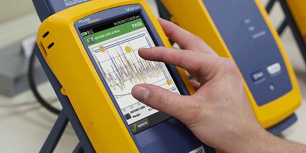
“Test equipment vendors are also mimicking smartphones and tablets with capacitive touchscreens, including gestures such as pinch/zoom. It’s nearly impossible these days not to mention the cloud, and the latest generation of certification testers will begin to allow technicians to send their results to the cloud from the field. The advantages are numerous. If a technician sends them each day, the results are safe and secure—even though his tester may not be; theft of test equipment is becoming an issue. Managers can monitor progress remotely, and [there] is no need for a laptop on-site to download results,” Young said.
About The Author

GRIFFIN, a construction journalist from Oklahoma City, can be reached at [email protected].