You're reading an older article from ELECTRICAL CONTRACTOR. Some content, such as code-related information, may be outdated. Visit our homepage to view the most up-to-date articles.
Understanding TIA-568 can lead to more consistent loss measurements:
TIA standards for structured cabling include many details on the installation and testing of fiber optic cabling, but some of the requirements are unusual and not well-explained, although they can be very important to the installer. One in particular, the use of a “mandrel wrap” on a multimode launch reference cable to create a standardized test condition, has always been a source of confusion. Why do you need to wind the launch cable around a mandrel anyway? How does it work? What effect does it have on the measurement?
To comprehend the effect of a mandrel wrap, you must first understand how light is transmitted in multimode fiber. This fiber is called multimode because it transmits light in many modes or rays of light, which travel in curving (sine wave) paths (see Figure 1). Notice the light in some modes stays close to the center of the fiber core (called lower-order modes), while others (called higher-order modes) go close to the edge of the core. The term “mode power distribution” (MPD) describes this phenomenon.
Looking at this diagram, you can see the lower-order modes traveling close to the center of the core actually travel shorter paths through the fiber than those traveling all the way to the outside of the core. The higher-order modes suffer more attenuation simply because they travel through more glass in their longer paths down the fiber. Thus, as you go down a length of fiber, the higher-order modes are attenuated more, so that the light in the fiber becomes more concentrated in the center of the core, as shown in the lower fiber.
This concentration of light toward the center of the core has two effects that reduce the loss of a cable plant. First, the attenuation coefficient (expressed in dB/km) of the fiber itself decreases along the fiber as the higher order modes are more attenuated, leaving only the lower loss central modes. This effect may take 1 to 2 km to reach equilibrium, and the attenuation coefficient of the fiber can be considerably less, as much as 1 dB/km at 850 nm at the end of the second kilometer. Secondly, as the light concentrates in the center of the core, the loss at connectors or splices is reduced, as the geometric offset of a connector becomes less a factor (see Figure 2).
The result of this is that the measurement you make of loss is dependent on the distribution of light in the fiber. Even on a short, 100m link, the fiber loss can vary by 0.1 dB or more, and the difference on every connection in the link can be as much as several tenths of a dB. If a link has four connections, the variations of the measurement caused by modal effects can be as much as 0.5 dB, while the entire link could have a loss of only 1.5 dB.
Sources affect MPD. LED sources tend to have diverging light outputs that couple light into the higher-order modes. Lasers, like the VCSELs used on most high-speed networks, concentrate light in the center of the core. So, a VCSEL will generally have lower loss in a cable plant than an LED.
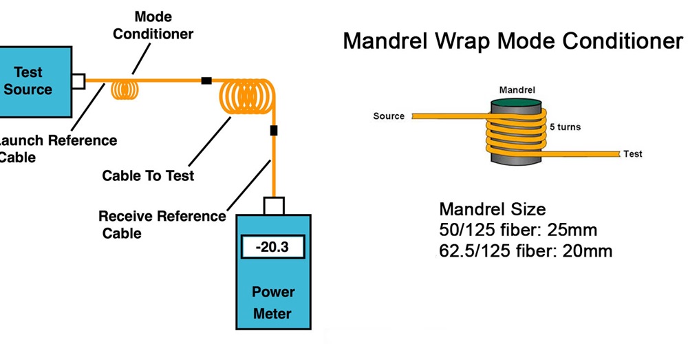
This uncertainty caused by MPD has led to the creation of standard test conditions. TIA-568 calls for a LED test source and a launch reference cable wrapped around a mandrel or rod, which attenuates the higher order modes in a fairly controlled fashion. Using a mandrel of a specified size for each type of fiber (see table below) will make the measured loss more predictable and—this is important—lower.
In my experience, most installers are not aware of this requirement in TIA-568 and, therefore, do not use this test method. This can be a big mistake, as this test method will always give lower loss when testing any multimode link. Not using a mandrel wrap means you are starting with a handicap, so it is to your advantage to understand and use this method properly.
About The Author

HAYES is a VDV writer and educator and the president of the Fiber Optic Association. Find him at www.JimHayes.com.