When making any kind of test, it is important to set test conditions to make measurements that are relevant and reproducible. In fiber optics, we test fiber optic cables, especially the installed cable plant, with a test setup similar to how the cable plant will be used with communications equipment.
The fiber optic communications equipment connects to the cable plant with patchcords, but when testing the cable plant, we use reference cables. They are high-quality cables that match the fiber and connectors on the cable plant.
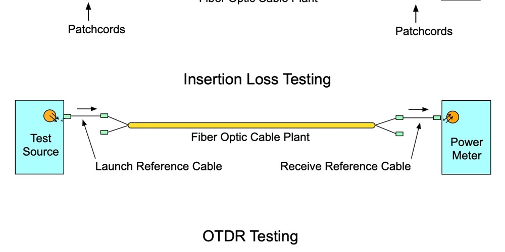
The purpose of these reference cables is to connect the test equipment to the cable plant for testing and, at the launch end, set the test source output launch conditions (e.g., modal conditions for multimode fiber) and test the connection at the end of the cable plant. At the receiver end, the reference cable is used to test the connection at the end of the cable plant and measure the optical loss.
The test setups for insertion loss testing with a light source and power meter (sometimes called an optical loss test set) and an optical time domain reflectometer (OTDR) are almost identical, but the reference cables are not exactly the same. For insertion loss testing, the launch and reference cables are typically 1-3 meters long. OTDRs need longer cables.
Insertion loss testing
Insertion loss testing uses a test source of a type and wavelength that matches the communications system to be used on the cable plant. A power meter measures the output of the source and sets that as the reference power for measuring loss. The test source and meter are connected as shown below and measure the loss of the cable plant, including the connections on either end.

Insertion loss testing requires setting the reference power for measuring loss, which is referred to as the “0 dB” reference. The power meter measures the reference and stores that information to use in measuring the end-to-end loss of the cable plant. Setting the 0 dB reference has three different options, depending on the fiber optic connectors on the instruments and the cable plant.

The one-cable reference is used when the connector type on the instruments matches the connectors on the cable plant (e.g., both use SC connectors). After setting the 0 dB reference, the meter is disconnected and a receive cable attached to it. The source launch reference cable is connected to one end of the cable to be tested while the receive reference cable and meter is connected to the other end, and a measurement of loss is made. This method is generally the preferred method of testing loss.
Note: Once the 0 dB reference is set, do not disconnect the launch cable from the source. Doing that will change the 0 dB reference set and will require setting it again.
The two-cable reference can be used when the connectors on the instruments and the cable plant do not match (e.g., SC connectors on the instruments and LC on the cable plant). The reference cables will be hybrid cables: SC on one end and LC on the other. After setting the reference, the two cables are disconnected at the middle connection and attached to the cable being tested, and the loss is measured.
The three-cable method is used when the connectors on the instruments and the cable plant do not match or the connectors on the cable plant are plug/jack connectors, such as the MPO connector with alignment pins on one connector and holes on the mating connector. Here the two cables on the ends are hybrid cables with connectors on one end to mate to the instruments and connectors on the other end to mate with the third reference cable. The third reference cable is a short cable with connectors that are identical to the cable plant being tested. After the 0 dB reference is set using all three cables, the center cable is replaced by the cable plant to be tested and the loss measured. This is sometimes called a cable substitution test.
The cable plant loss you measure will depend on the reference method you use. The two-cable method includes one connection between reference cables when you set the 0 dB reference, and the three-cable method includes two connections. The loss you measure with the two- and three-cable reference methods will be reduced by the loss of the connections included when setting the 0 dB reference.

Note: The “1c” in the diagram above is the loss of the connection when setting a 0 dB reference with two cables, and “2c” is the loss of the two connections included when using the three-cable reference method.
OTDR testing
OTDR testing can be done with one or two reference cables. Each cable has a different purpose.

The OTDR launch cable is used to overcome the “dead zone” of the OTDR caused by the high-power test pulse overloading the receiver circuitry. The OTDR launch cable must be long enough to allow the OTDR circuitry to recover. This varies according to the range of the OTDR, the width of the test pulse and the signal processing, but it should be fairly long. For single-mode long-distance tests, at least a 1-kilometer launch cable is recommended. For short-distance tests, such as FTTH cables using high-resolution OTDRs, the cable can be as short as 50-100 meters. Multimode cables are always short, so a cable of 50-100 meters is usually adequate.
The purpose of the receive reference cables is just to test the connection with the connector on the end of the cable under test. That leads to the requirement for a receive reference cable on the far end to mate with the far end of the cable.
Some OTDR tests are done with only a launch cable if the test is just to verify splices in a cable being installed and segments spliced together and if there is no connector on the far end.
Requirements for reference cables
There are some important requirements for reference cables used in insertion loss and OTDR testing:
- The fiber type matches the fiber in the cable plant being measured.
- Connectors can mate with instruments and connectors on cable plant, which may require hybrid cables for two- or three-cable reference methods.
- Cables for insertion loss measurements should be 1-3 meters long.
- Cables for OTDR testing should be sufficiently long for the launch cable to extend beyond the OTDR dead zone under test conditions and the receive cable should be long enough to be easily seen by the OTDR.
- Reference cables must be low loss when measured against each other.
- Testing requires compatible connector mating adapters.
Handling and testing of reference cables
Reference cables require special handling and frequent testing to ensure they are in good condition.
- Inspect with a microscope and clean regularly.
- Test against each other for insertion loss.
- Keep protective caps on connectors.
- Store in a safe place to prevent damage.
- Do not kink, twist or otherwise stress cables.
- Repair or replace when needed.
Follow these guidelines and your fiber optic testing will be more accurate and reliable.
About The Author

HAYES is a VDV writer and educator and the president of the Fiber Optic Association. Find him at www.JimHayes.com.