I assume most of you know how a fiber optic link transmits data by converting an electrical signal to optical at the transmitter and converting the light back to electrical signals at the receiver. That simple description is true for most networks, but as signals get faster and distances longer, the technologies get more complicated. I’m going to explain—and show graphically—how fiber optic links work and how fiber optic technology has been developed to allow faster and longer links.
A basic fiber optic link
In the simplest fiber optic links used for speeds up to about 10 gigabits/second (Gbps) look like this:
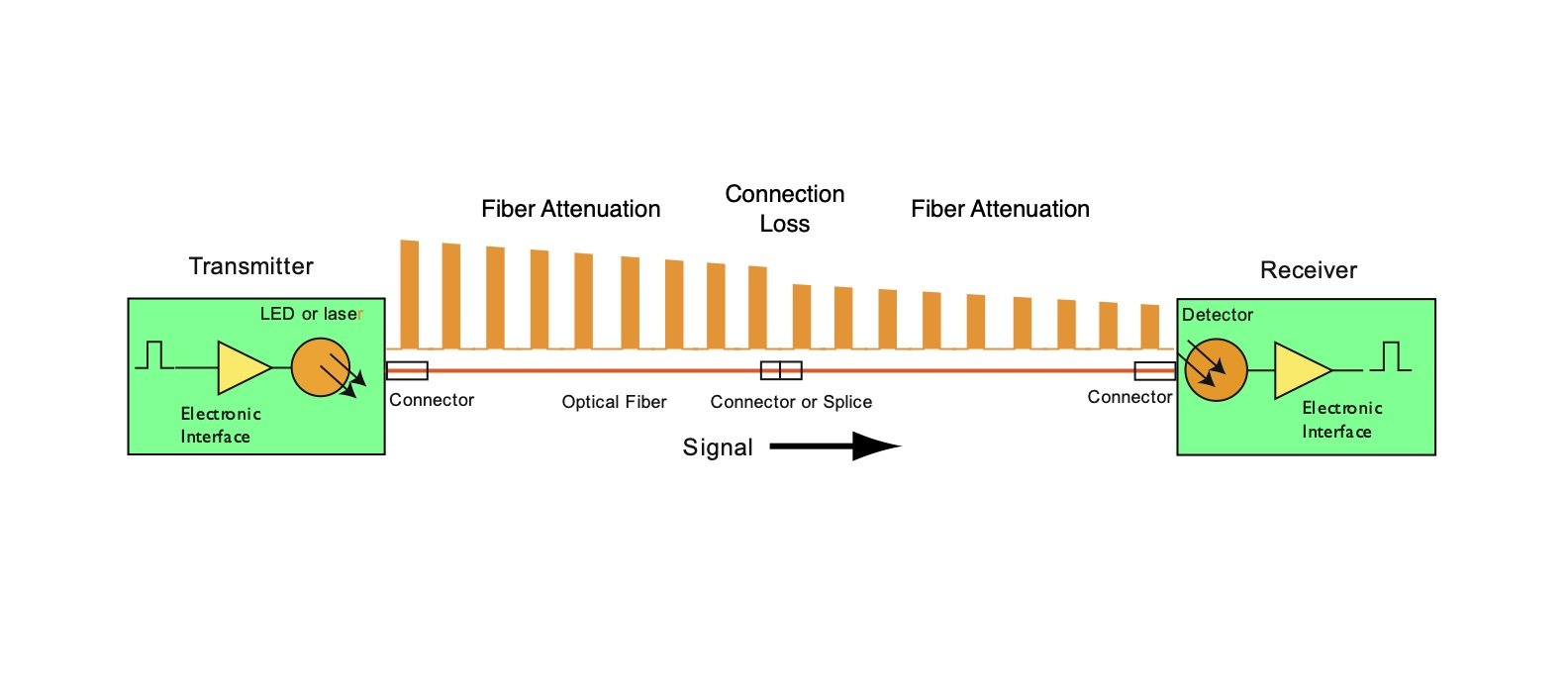
The input to the transmitter is a low-voltage electrical signal from the electronic equipment the link is connecting. The electronic interface in the transmitter converts the voltage pulse to a current pulse needed to drive the laser source, converting the electrical input to an optical output. The transmitter has a mechanical interface to couple the optical output into a fiber optic cable.
As the signal travels down the optical fiber, it will be attenuated by the fiber so the signal at the receiver end will be lower than the signal out of the transmitter. The signal may also be spread out by dispersion in the fiber as shown below, a factor in higher-speed systems.

At the receiver end, a detector captures light from the fiber and converts it to an electrical current. The electronics in the receiver convert the current from the detector into a voltage compatible with the electronics being connected by the fiber optic link. Most fiber optic links operate by using two fibers transmitting in opposite directions for a full duplex link. Full duplex means it can transmit and receive simultaneously.
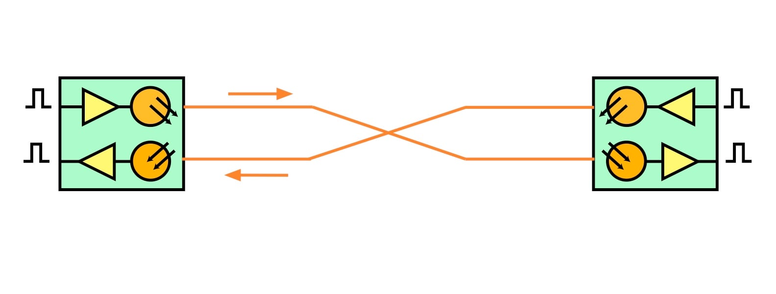
Some networks can transmit and receive over a single fiber, a technique used in a fiber to the home (FTTH) passive optical network (PON).
How data is transmitted
Fiber optic links are usually thought of as data links, and one assumes the data is all digital. That is true for telecom, the internet and local area networks (LANs), but some links like CATV actually use analog transmission.
What’s the difference between analog and digital? An analog link is transmitting data in the form of a continuous varying signal, so the information is in the amplitude and frequency of the signal. Radio and TV signals are mostly analog, and each of these signals is on a specific frequency for its channel, a feature of analog transmission.

A digital link sends data that is encoded in binary signals—“1s” and “0s”—pulses that represent digital values, so the information, which might be numbers from a spreadsheet, letters in a word or pixels in a picture, are encoded and transmitted as 1s and 0s.
Most links use simple encoding of the binary signal as no light being a 0 and a light pulse being a 1. That technique works up to about 10–25 Gbps for optical signals, limited by how fast the laser light source can be modulated (turned on and off). Years ago, when speeds were lower, LEDs were also used as sources, but they were limited to about 100–200 megabits/second (Mbps), too slow for most modern links, but ideal for inexpensive plastic fiber links connecting consumer electronics.
When speeds exceed the limit of modern lasers, there are several techniques used to achieve higher data rates. Datacom links on multimode fiber use parallel transmission. The high bit rate signal is split into multiple signals, e.g., 100 Gbps becomes ten 10-Gbps signals or four 25-Gbps signals, and each signal is transmitted on a single fiber, so the link requires 10 or 4 fibers in each direction—20 or 8 fibers for each duplex link.
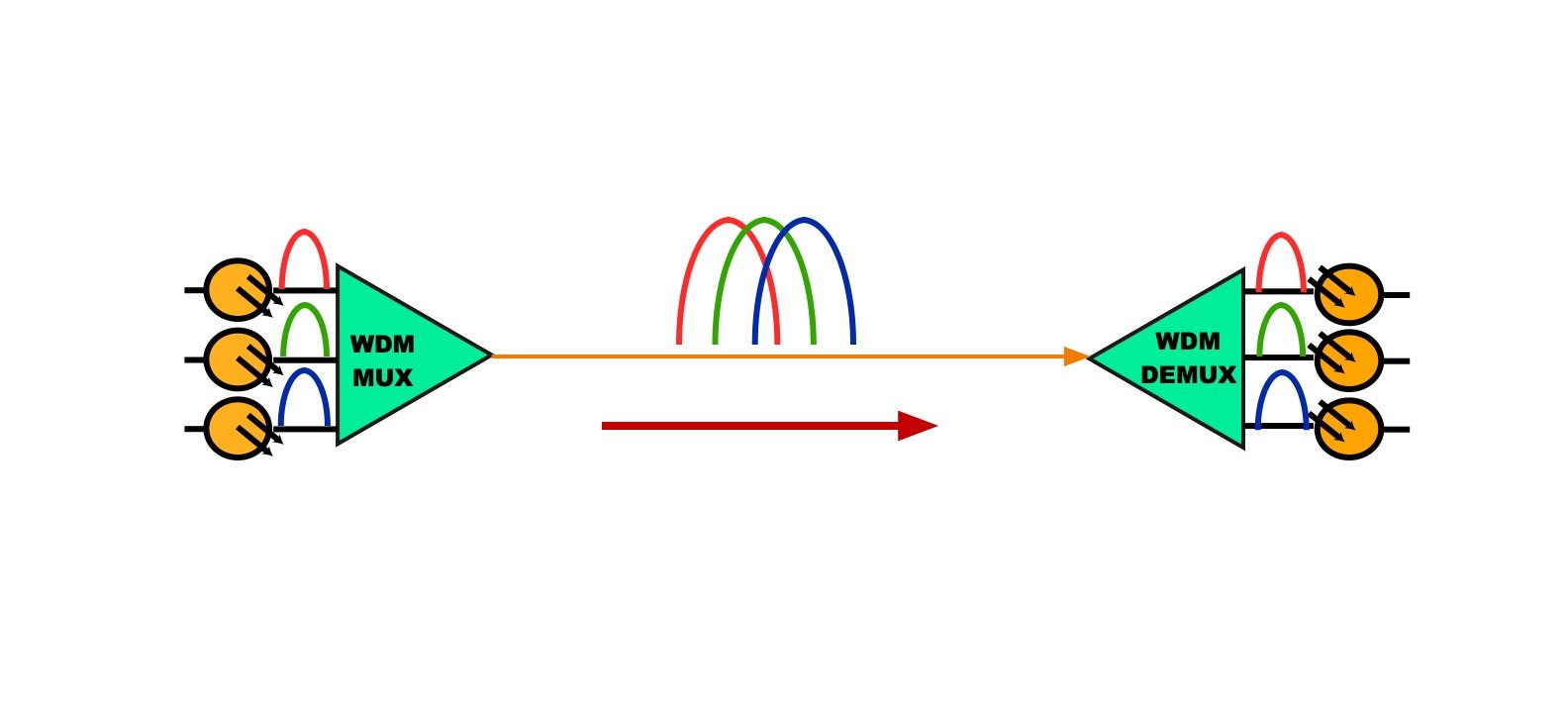
With single-mode telecom and datacom systems, wavelength division multiplexing (WDM) is used. The high bit rate signal is split into multiple signals, e.g., 100 Gbps becomes four 25-Gbps signals, and each signal is transmitted on a single fiber with a laser at a different wavelength of light. On long-distance and submarine cable systems, more than 100 channels can be transmitted through a single-mode fiber simultaneously with WDM. A multimode version of WDM exists but is rarely used.
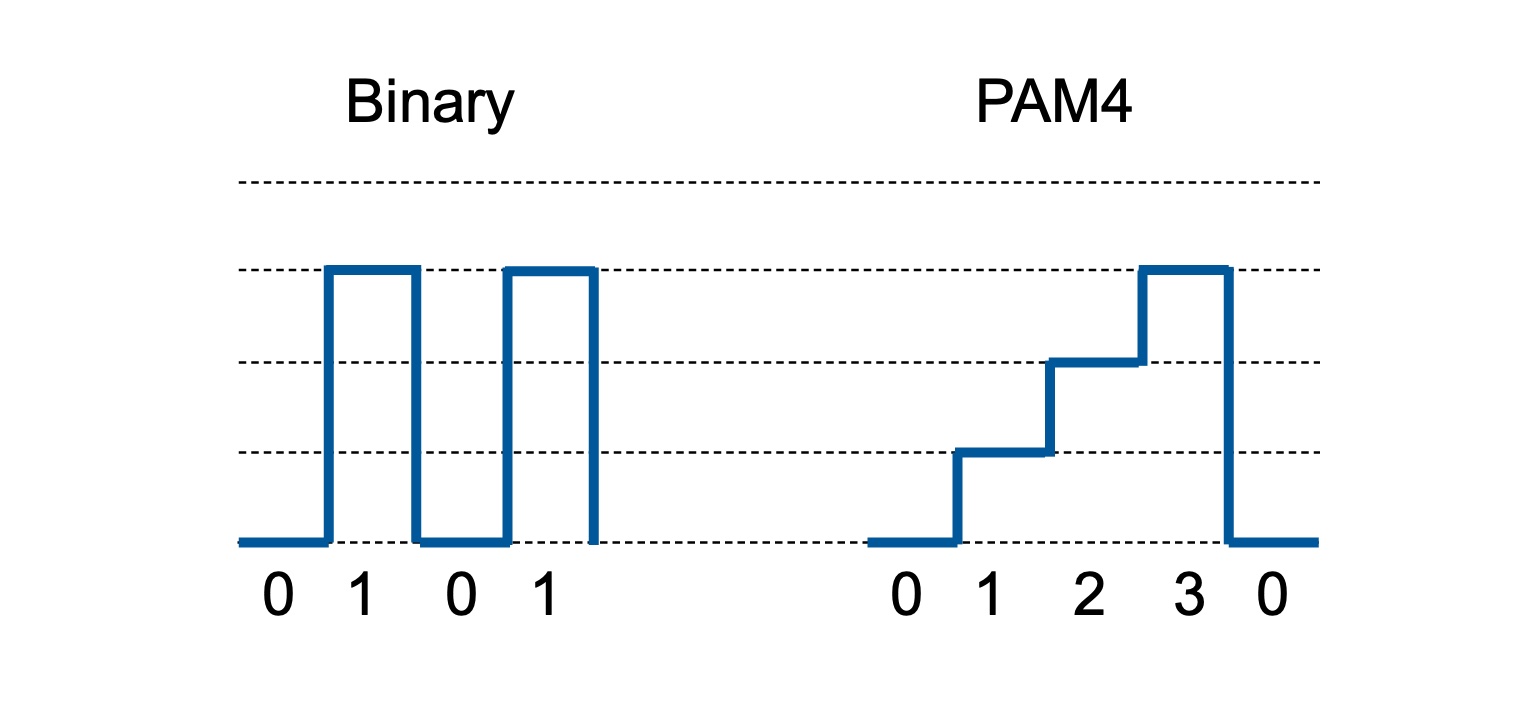
Another technique to increase data speeds is to encode more data into each bit. That is done by using the amplitude of the signal pulse to encode multiple bits, called pulse amplitude modulation (PAM). In the PAM 4 encoding shown below, two binary bits are encoded in a single pulse, doubling the bandwidth of the signal. This has been done for years in electrical signals, but has only recently been adopted in fiber optics and become available in fiber optic transceivers.
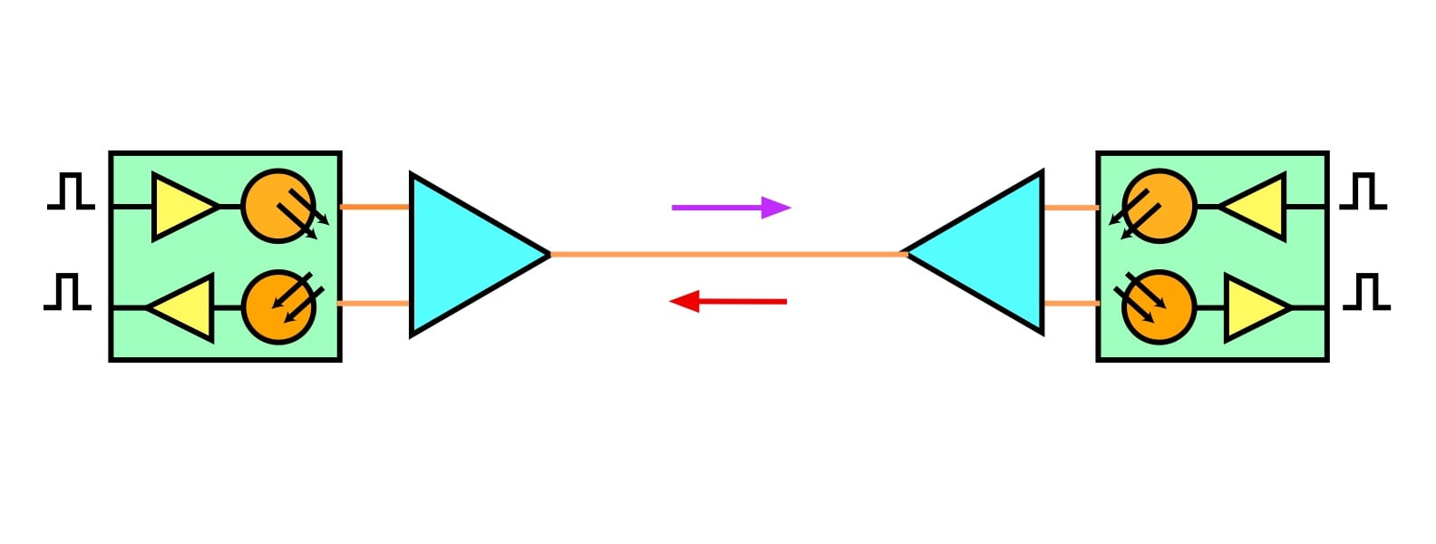
The next technique, coherent transmission, is much more complicated—borderline magic! Coherent transmission has been widely adopted for long-distance and submarine links because it is capable of bit rates of terabits/second (Tbps) and distances of thousands of kilometers. It’s also getting used for very high-speed links in data centers and supercomputing.
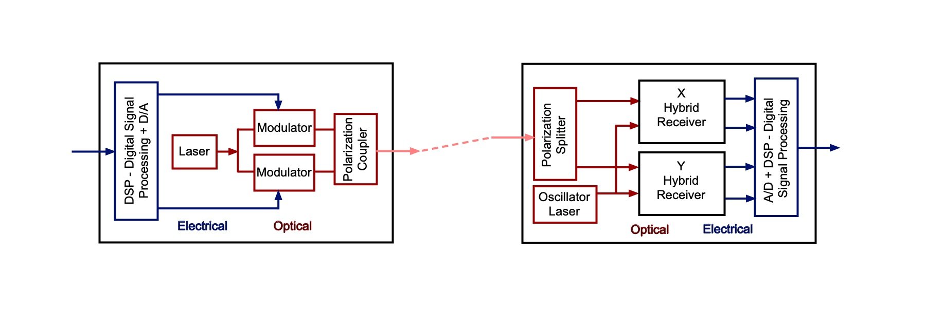
Coherent transmission requires much more complex transceivers. Coherent transmitters overcome the limited bandwidth of lasers by leaving the laser on all the time and modulating it externally using electro-optical modulators. The modulators are not just making ones and zeroes, but use PAM to encode more than one bit of data in a single pulse. The outputs of the modulators are coupled into the fiber as two beams of different polarization that are multiplexed on the same fiber. Thus, the coherent transmitter can encode optical data in both the amplitude of the signal pulse and the polarization of the light in the fiber, making it possible to encode very high data rates. In coherent systems, the receiver must do the hardest work, decoding the complex incoming signal into usable data.
All of these types of fiber optic links are used today, with the choice of application being made based on technical requirements and, of course, cost.
About The Author

HAYES is a VDV writer and educator and the president of the Fiber Optic Association. Find him at www.JimHayes.com.