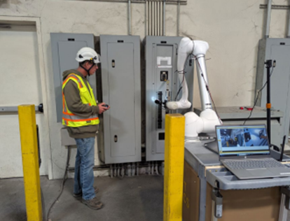
Here is a common mistake I still see: You are about to perform energized work on a 480V motor control center. However, during the arc flash risk assessment, you found no incident energy calculations to use for selecting arc-rated protective clothing and equipment. No problem—you decide to use NFPA 70E Table 130.7(C)(15)(a), Arc Flash PPE Categories. With categories ranging from 1 to 4, the required PPE is then selected from Table 130.7(C)(15)(c), Personal Protective Equipment (PPE). The larger the category number, the greater the PPE requirements and associated arc rating.
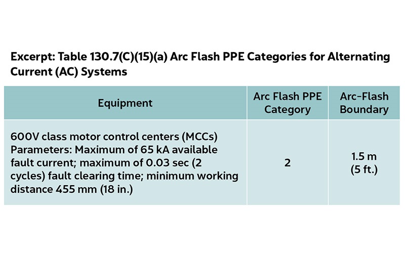
Looking at the excerpt from the PPE category table shown here, you determine that PPE Category 2 is sufficient. You are now good to go, right? Wrong!
Why? Because there is more to the table than simply selecting a PPE category. There are very important parameters for each type of equipment and associated category listed, including the maximum available fault (short circuit) current, the maximum fault clearing time and the minimum working distance. While working distance—the distance between a person’s face and chest and a potential arc source—is typically well understood, the other two parameters are not and frequently ignored.
Evolution of the tables
The tables were first introduced in the 2000 edition of NFPA 70E as a method for determining appropriate arc-rated protective clothing and equipment for arc flash hazard protection. This was before IEEE 1584, IEEE Guide for Performing Arc-Flash Hazard Calculations, was first published in 2002 and became an integral part of conducting incident energy calculations for arc flash studies.
They were originally called hazard risk category (HRC) tables, which factored in risk. This meant there could be different HRCs at the same piece of equipment, depending on the task’s associated risk.
The risk element was removed from the 2015 edition of NPFA 70E.The tables are now known as Arc Flash PPE Categories and address AC and DC power systems. They evolved over time, eliminating a possible –1 category and later removing category 0. The remaining important details are the maximum fault current and clearing time.
Fault current and clearing time
Fault current and clearing time are the two main variables that define the severity of an arc flash. Fault current flows to the point of the fault/arc flash and can be tens of thousands of amperes. The greater the current, the more intense the arc flash can be.
The arc flash duration is normally defined by how long it takes an upstream protective device to clear the fault. The longer the duration, the greater the overall incident energy exposure. The protective device considered to define the arc duration should be in a location that would be unaffected by the arc flash. So a main protective device in the same equipment enclosure such as a panelboard is not normally considered, as it could be affected by the arc flash. Instead, use a device upstream in a different enclosure or location.
Service entrance equipment can pose a particular problem, since the next device upstream would likely be from the electric utility company. Utility protective devices are often much slower to minimize nuisance interruptions during events such as energizing a transformer that results in a large magnetizing inrush current.
OK, now what?
So how are the fault current and fault clearing time determined? That’s the problem, which is why it is sometimes incorrectly ignored. Available fault current and device clearing times can require a complex analysis, and they are addressed in standards such as IEEE Std 551 (the Violet Book), IEEE Std 3002.3 and IEEE Std 242 (the Buff Book).
There are also approximation methods for determining the fault current based on transformer size and impedance. The electric utility can often provide the available fault current at the service entrance. The NEC has a few requirements for field marking the available fault current on equipment, such as in Section 110.24, Available Fault Current, which is helpful if the equipment has such a label.
Determining the clearing time may require reviewing the upstream protective device’s operating characteristics, known as a time current curve. Many protective devices will clear a fault within a few electrical cycles. However, this depends on the actual device, settings and available fault current.
This is not meant to discourage using the NFPA 70E tables—quite the contrary. In the absence of incident energy calculations, the tables remain a good alternative. Just don’t ignore the parameters.
Header image source: NFPA
About The Author

PHILLIPS, P.E., is founder of brainfiller.com and provides training globally. He is Vice-Chair of IEEE 1584 Arc Flash Working Group, International Chair of IEC TC78 Live Working Standards and Technical Committee Member of NFPA 70E. He can be reached at [email protected].