You're reading an older article from ELECTRICAL CONTRACTOR. Some content, such as code-related information, may be outdated. Visit our homepage to view the most up-to-date articles.
Table 310.15(B)(16) in the National Electrical Code (NEC) provides allowable or maximum ampacities for insulated conductors rated up to and including 2,000 volts (V). When sizing conductors, more is involved than just looking in Table 310.15(B)(16) and selecting a conductor based on the ampacity shown. The ampacities in this table are based on no more than three current-carrying conductors in a raceway, cable or earth (directly buried). The ampacities are also based on an ambient temperature of 30°C. When there are more than three current-carrying conductors and/or the ambient temperature is other than 30°C, the table ampacities must be adjusted and/or corrected. Therefore, factors, such as ambient temperature and the number of current-carrying conductors, must be considered when sizing conductors. Other factors, such as the temperature ratings of the terminations and continuous loads, also must be considered when sizing conductors.
Last month’s column covered both the ambient temperature correction factor and the adjustment factor for adjacent current-carrying conductors. This month, the discussion continues with other factors that must be considered when sizing conductors.
This series on sizing conductors previously covered continuous loads but only when the ambient temperature was 30°C and the number of current-carrying conductors did not exceed three. If the ambient temperature is something other than 30°C and/or there are more than three current-carrying conductors in a raceway, cable or earth (directly buried) and the load is continuous, it will be necessary to perform separate calculations.
Perform the first calculation to meet the requirements for termination temperature limitations; with this calculation, continuous loads shall be included at 125 percent. Perform the second calculation to meet the requirements for ambient temperature in 310.15(B)(2); with this calculation, apply the Table 310.15(B)(3)(a) adjustment factors if there are more than three current-carrying conductors in the raceway, cable or earth (directly buried).
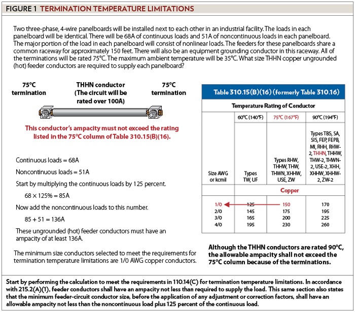
After performing both calculations, if the results are different size conductors, select the largest conductor. The largest conductor shall be protected against overcurrent in accordance with its ampacity specified in 310.15, unless otherwise permitted or required in 240.4(A) through (G). For example, two three-phase, 4-wire panelboards will be installed next to each other in an industrial facility. The loads in each panelboard will be identical. There will be 68 amperes (A) of continuous loads and 51A of noncontinuous loads in each panelboard. The major portion of the load in each panelboard will consist of nonlinear loads. The feeders for these panelboards share a common raceway for approximately 150 feet. There will also be an equipment grounding conductor in this raceway. All terminations will be rated 75°C. The maximum ambient temperature will be 35°C. What size THHN copper ungrounded (hot) feeder conductors are required to supply each panelboard?
Start by performing the calculation to meet the requirements in 110.14(C) for termination temperature limitations. In accordance with 215.2(A)(1), feeder conductors shall have an ampacity not less than required to supply the load. This same section also states that the minimum feeder-circuit conductor size, before the application of any adjustment or correction factors, shall have an allowable ampacity not less than the noncontinuous load plus 125 percent of the continuous load. In this example, the continuous load is 68A. After multiplying by 125 percent (or 1.25), the continuous load is 85A (68 1.25 = 85). Now add the noncontinuous loads to this number. These ungrounded feeder conductors must have an ampacity of at least 136A (85 + 51 = 136). Although the THHN conductors are rated 90°C, the allowable ampacity shall not exceed the 75°C column because of the terminations [see 110.14(C)(1)(b)]. The minimum size conductors, from the 75°C column, are 1/0 AWG copper conductors. Therefore, the minimum size conductors selected to meet the requirements for termination temperature limitations are 1/0 AWG copper conductors (see Figure 1).
Now perform a second calculation to meet the requirements for ambient temperature correction factors and Table 310.15(B)(3)(a) adjustment factors. Ambient temperature correction factors and Table 310.15(B)(3)(a) adjustment factors are also referred to as the “conditions of use.” As previously mentioned, the minimum feeder-circuit conductor size, before the application of any adjustment or correction factors, shall have an allowable ampacity not less than the noncontinuous load plus 125 percent of the continuous load [215.2(A)(1)].
This section seems to be saying to add the continuous load at 125 percent to the noncontinuous load at 100 percent and then size the conductors in accordance with adjustment and/or correction factors. But that is not what it is saying.
As defined in Article 100, ampacity is the maximum current, in amperes, that a conductor can carry continuously under the conditions of use without exceeding its temperature rating. As previously mentioned, the conditions of use are ambient temperature and the number of current-carrying conductors in a raceway or cable. When correcting the ampacity because of ambient temperature and/or adjusting the ampacity because of more than three current-carrying conductors in a raceway or cable, use the actual load: use 100 percent of the noncontinuous load and 100 percent of the continuous load. In this example, the noncontinuous load is 51A, and the continuous load is 68A. Therefore, after derating for ambient temperature and for more than three current-carrying conductors in the raceway, the conductors shall have an allowable ampacity of at least 119A (68 + 51 = 119), not 136A.
Because the major portion of the load in each panelboard will consist of nonlinear loads, the neutral conductors shall be counted as current-carrying conductors [see 310.15(B)(5)(c)]. Since there are two three-phase, 4-wire feeders in one raceway and the neutrals are counted, there are eight current-carrying conductors in this one raceway. The adjustment factor from Table 310.15(B)(3)(a) for eight current-carrying conductors is 70 percent (or 0.70). The maximum ambient temperature in this example will be 35°C. Conductors with temperature ratings higher than specified for terminations shall be permitted to be used for ampacity adjustment, correction or both [110.14(C)]. The temperature rating for a THHN conductor is 90°C. Although the terminations limit the ampacity to the 75°C column, it is permissible to use the ampacity in the 90°C column for correction and adjustment. Therefore, the Table 310.15(B)(2)(a) correction factor, in the 90°C column, for an ambient temperature of 35°C is 0.96.
To find the minimum ampacity, divide the actual load by the adjustment and correction factors. After dividing the load of 119A by the adjustment factor, the ampacity is 170A (119 ÷ 0.70 = 170). After dividing 170A by the correction factor of 0.96, the ampacity is 177A (170 ÷ 0.96 = 177.08 = 177). Now select a copper conductor from the 90°C column of Table 310.15(B)(16) that has an ampacity of at least 177A. The minimum size 90°C conductors selected to meet the requirements for ambient temperature correction factors and Table 310.15(B)(3)(a) adjustment factors are 2/0 AWG copper conductors (see Figure 2).
Because the results of the two calculations are different size conductors, compare them, and select the largest. The minimum size selected to meet the requirements for termination temperature limitations are 1/0 AWG copper conductors. The minimum size selected to meet the requirements for ambient temperature correction factors and Table 310.15(B)(3)(a) adjustment factors are 2/0 AWG copper conductors. Therefore, the minimum size ungrounded (hot) feeder conductors required to supply each panelboard are 2/0 AWG copper conductors.
To verify that the conductor selected is the correct size, multiply the conductor’s allowable ampacity by the adjustment and correction factors. After derating, the conductors must have an allowable ampacity of at least 119A (68 + 51 = 119). Start by finding the conductor and the listed ampacity in Table 310.15(B)(16). The allowable ampacity for a 2/0 AWG THHN copper conductor, in the 90°C column, is 195A. Multiply 195A by the Table 310.15(B)(3)(a) adjustment factor of 70 percent (195 0.70 = 136.5). Now multiply 136.5A by the Table 310.15(B)(2)(a) correction factor of 0.96 (136.5 0.96 = 131.04 = 131). After derating because of ambient temperature and the number of current-carrying conductors, the maximum ampacity is 131A. Since the actual load is 119A, 2/0 AWG THHN copper conductors are permitted (see Figure 3).
Next month’s column continues the discussion of sizing conductors.
MILLER, owner of Lighthouse Educational Services, teaches classes and seminars on the electrical industry. He is the author of “Illustrated Guide to the National Electrical Code” and “The Electrician’s Exam Prep Manual.” He can be reached at 615.333.3336, [email protected] and www.charlesRmiller.com.
About The Author
Charles R. Miller, owner of Lighthouse Educational Services, teaches custom-tailored seminars on the National Electrical Code and NFPA 70E. He is the author of “Illustrated Guide to the National Electrical Code” and “Electrician's Exam Prep Manual.” He can be reached at 615.333.3336 and [email protected]. Connect with him on LinkedIn.


