Emergency systems, legally required standby systems and optional standby systems are often supplied by generators as the standby source if the normal (utility) source is interrupted. Emergency and legally required standby system power must be restored after not more than a 10-second time frame. This is typically accomplished through the use of transfer equipment that is identified for emergency use. An optional standby system design can employ either manual or automatic transfer equipment and does not have to meet the 10-second transfer requirement.
Generators are power sources that are often required to be grounded as separately derived systems. The type of transfer equipment determines the method of making the system grounding connections at a generator. Informational Note No. 1 following Section 250.30 describes the relationship between the transfer equipment and an alternate source (separately derived system) and how the system grounding connections must be made for the generator.
First, if a generator’s transfer switch includes a switching action in the grounded (usually a neutral) conductor, the generator has to be grounded as a separately derived system in accordance with 250.30(A). The reason is because, in the normal power mode, the grounded (usually the neutral) conductor is connected to the service grounding electrode, in the standby mode, the grounded (neutral) conductor is switched over to the generator source, which is grounded as a separately derived system. The result is that, in either position of the transfer switch, the electrical system remains grounded. If the transfer equipment applied in the design does not provide a switching action in the grounded conductor, the system produced by the generator output remains grounded through the service grounding electrode system, with the transfer switch in either normal or standby mode.
Chapter 7 of the National Electrical Code (NEC) contains important requirements that directly relate to signage required for service equipment on buildings or occupancies that have backup systems for emergency, legally required or optional standby power. These signs convey vital information. As a reminder of the information in Section 90.3, the rules in Chapter 7 supplement or modify the rules in chapters 1 through 7, and in this case, the supplements in Chapter 7 are more restrictive.
First, sections 700.7, 701.7 and 702.7 contain identical requirements. Subdivision (A) of each section contains a requirement to install a sign at the service equipment that denotes there is a standby source(s) and where it is located. This is important for first responders, so they have an initial indication that opening the service disconnect only removes the normal electric service to the building(s) or structure(s) served. The sign notifies them of the backup power source and its location so they can disable it if necessary.
Subdivision (B) in each of these sections contains a warning sign requirement that is intended to protect persons from shock hazards. If the standby source has transfer equipment that does not provide a switching action in the grounded (usually a neutral) conductor when transferring to the standby mode, the generator grounding electrode connection is dependent upon the grounding electrode connection in the service equipment.
The exact wording of the warning sign that must be provided on the service equipment reads as follows: “Warning: shock hazard exists if grounding electrode conductor or bonding jumper connection in this equipment is removed while alternate source(s) is energized.”
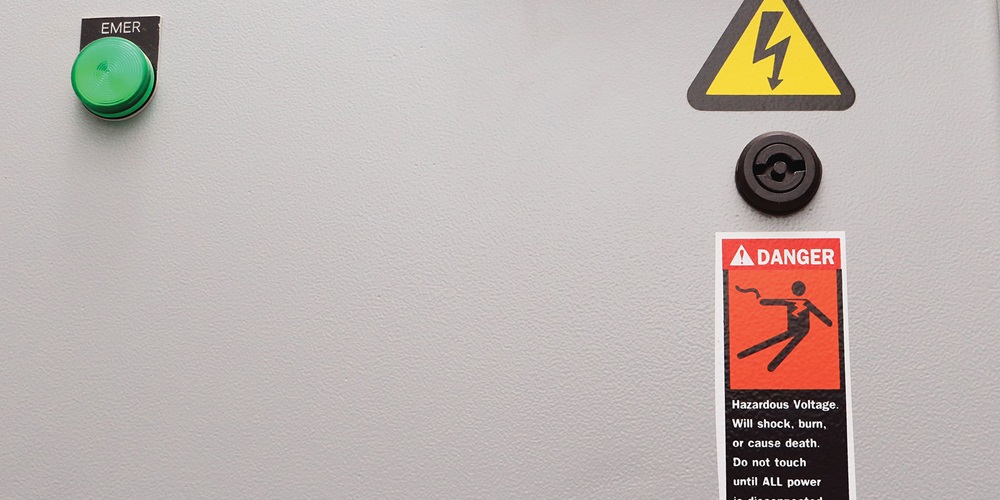
The signal word “warning” dictates the sign’s colors should be white, orange and black. Note that a danger sign requires the colors white, red and black, and a caution sign requires the colors white, yellow and black. Many requirements throughout the NEC call for a warning, danger or caution sign(s). Within these rules typically exists a reference to NEC 110.21(B), which addresses the development of field-applied hazard markings. See Section 110.21(B) and informational notes that reference ANSI Z535.4. Note that, in 110.21(B)(3), these signs or markings must be suitable for the environment involved, meaning they must be able to withstand the elements and remain effective.
In summary, two common requirements for signage exist in sections 700.7, 701.7 and 702.7. One of these requirements is to develop a normal sign indicating the type and location of each alternate power source. The other is a hazard marking warning sign that warns of potential shock hazards to those working in the equipment and disconnecting grounding electrode conductors or bonding jumpers within the equipment. This warning sign requirement triggers additional requirements in Section 110.21(B).
About The Author

Michael Johnston
NECA Executive Director of Codes and Standards (retired)JOHNSTON, who retired as NECA’s executive director of codes and standards in 2023, is a former member and chair of NEC CMP-5 and immediate past chair of the NEC Correlating Committee. Johnston continues to serve on the NFPA Standards Council and the UL Electrical Council. Reach him at [email protected].


