Generators are commonly installed for buildings or structures requiring emergency systems, legally required standby systems or optional standby power systems. In many designs, the generator is located outside the building or structure, requiring feeder conductors from the generators to supply the standby system for the building or structure, and when they are located outside the building or structure, the requirements in National Electrical Code (NEC) Article 225 Part II apply. This column reviews the basic grounding requirements for generators.
Generators are power sources and are often required to be grounded as separately derived systems. How the system grounding connections are made at a generator is determined by the type of transfer equipment installed.
An informational note following Section 250.30 describes the relationship between the transfer equipment and how the system grounding connections must be made for the generator. First, if a transfer switch for a generator includes a switching action in the grounded (usually a neutral) conductor, then the generator has to be grounded as a separately derived system in accordance with all applicable requirements in 250.30(A). This is because, in the normal power mode, the grounded (neutral) conductor is connected to the service grounding electrode. In standby mode, the grounded (neutral) conductor is switched over to the generator source, which is grounded as a separately derived system. The result is that, in either position of the transfer switch, the electrical system remains grounded. If there is no switching action in the grounded (neutral) conductor through the transfer equipment, then the generator system remains grounded with the transfer switch in either normal or standby position.
Section 250.35 provides requirements related to installing an effective ground-fault current path, which is covered generally in Section 250.4(A). The performance concepts of 250.35 emphasize providing an effective ground-fault current path with the supply conductors of the generator to the first disconnecting means or equipment supplied. Generators grounded as separately derived systems meet this requirement when installed according to the rules in 250.30(A). If the generator is not grounded as a separately derived system, an effective ground-fault current path must be provided in accordance with either 250.35(A) or (B). This means an equipment bonding jumper has to be installed between the generator equipment grounding terminal and the equipment grounding terminal bar or bus of the enclosure supplied by the system.
The sizing requirements for this equipment bonding jumper are related to the location of the first system overcurrent device. If the equipment bonding jumper is on the supply side of the first system overcurrent device, the equipment bonding jumper is sized as a supply-side bonding jumper and must be installed in accordance with 250.102(C). This means the minimum size must be based on Table 250.102(C) or the 12.5 percent sizing rule based on the total circular mil area of the largest ungrounded phase conductors connected to the generator. The equipment grounding conductor or equipment bonding jumper installed on the load side of generator overcurrent devices must be sized in accordance with 250.102(D) covering load side equipment bonding jumper installations. Table 250.122 is required to be used for establishing the minimum size and is based on the rating of the overcurrent device installed to protect the conductors supplied by the generator system.
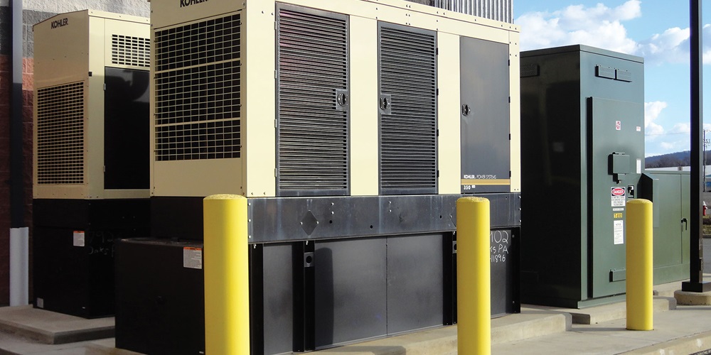
If generators are installed outdoors, there is often an auxiliary grounding electrode specified in the design. The NEC does not require this auxiliary electrode, but when it is installed, specific requirements must be met. The auxiliary electrode provides a direct connection (reference) to the earth that is local to the generator. This ground (earth) connection is in addition to the grounding and bonding required by either 250.30(A) or 250.35 as covered above. The auxiliary (supplementary) grounding electrode must be connected to the equipment grounding conductor in addition to the frame of the generator. The earth is not permitted as an effective ground-fault current path. When auxiliary supplementary grounding electrodes are installed for equipment, they are not required to meet the 25-ohm requirements specified in 250.53(A)(2) exception as indicated in 250.54.
In summary, generators are power sources that are often required to be grounded in accordance with the rules for separately derived systems. Section 250.30 Informational Note No. 1 provides essential information that assists users in determining generator system grounding requirements. The transfer equipment applied in the design is the key determining factor for grounding a generator as a separately derived system.
An effective ground-fault current path is required between the generator and the equipment supplied by the system.
About The Author

Michael Johnston
NECA Executive Director of Codes and Standards (retired)JOHNSTON, who retired as NECA’s executive director of codes and standards in 2023, is a former member and chair of NEC CMP-5 and immediate past chair of the NEC Correlating Committee. Johnston continues to serve on the NFPA Standards Council and the UL Electrical Council. Reach him at [email protected].