You're reading an older article from ELECTRICAL CONTRACTOR. Some content, such as code-related information, may be outdated. Visit our homepage to view the most up-to-date articles.
Article 314 C Outlet, Device, Pull and Junction Boxes; Conduit Bodies; Fittings; and Manholes
314.16(B) Box-Fill Calculations
Article 314 of the National Electrical Code contains requirements pertaining to the installation and use of all boxes and conduit bodies used as outlet, device, junction or pull boxes, depending on their use. As indicated in the title, more than just boxes are covered in Article 314. This article also covers manholes and other electric enclosures intended for personnel entry. Article 314 also includes installation requirements for fittings used to join raceways and to connect raceways and cables to boxes and conduit bodies. Prior to the reorganization of articles in the 2002 edition, Article 314 was Article 370. Provisions for calculating the minimum-size outlet, device, or junction box (or conduit body) or the maximum numbers and sizes of conductors permitted in a box (or conduit body) are in 314.16. Specifications for box-volume calculations are in 314.16(A) and box-fill calculations are in 314.16(B). Last month's Code In Focus concluded with device or equipment fill in 314.16(B)(4). This month, the discussion begins with equipment-grounding conductor fill in 314.16(B)(5).
314.16(B)(5) Equipment-Grounding Conductor Fill
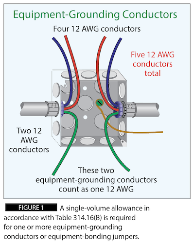
Where one or more equipment-grounding conductors or equipment-bonding jumpers enter a box, a single volume allowance in accordance with Table 314.16(B) shall be made based on the largest equipment-grounding conductor or equipment-bonding jumper present in the box. Equipment-grounding conductors and equipment-bonding conductors are not counted the same as other conductors. Each grounded (neutral) conductor and each ungrounded (hot) conductor, originating outside the box and terminating inside the box, counts as one conductor. One equipment-grounding conductor or equipment-bonding conductors counts as one conductor. Two equipment-grounding conductors or equipment-bonding conductors, originating outside the box and terminating inside the box, also count as only one conductor (see Figure 1).
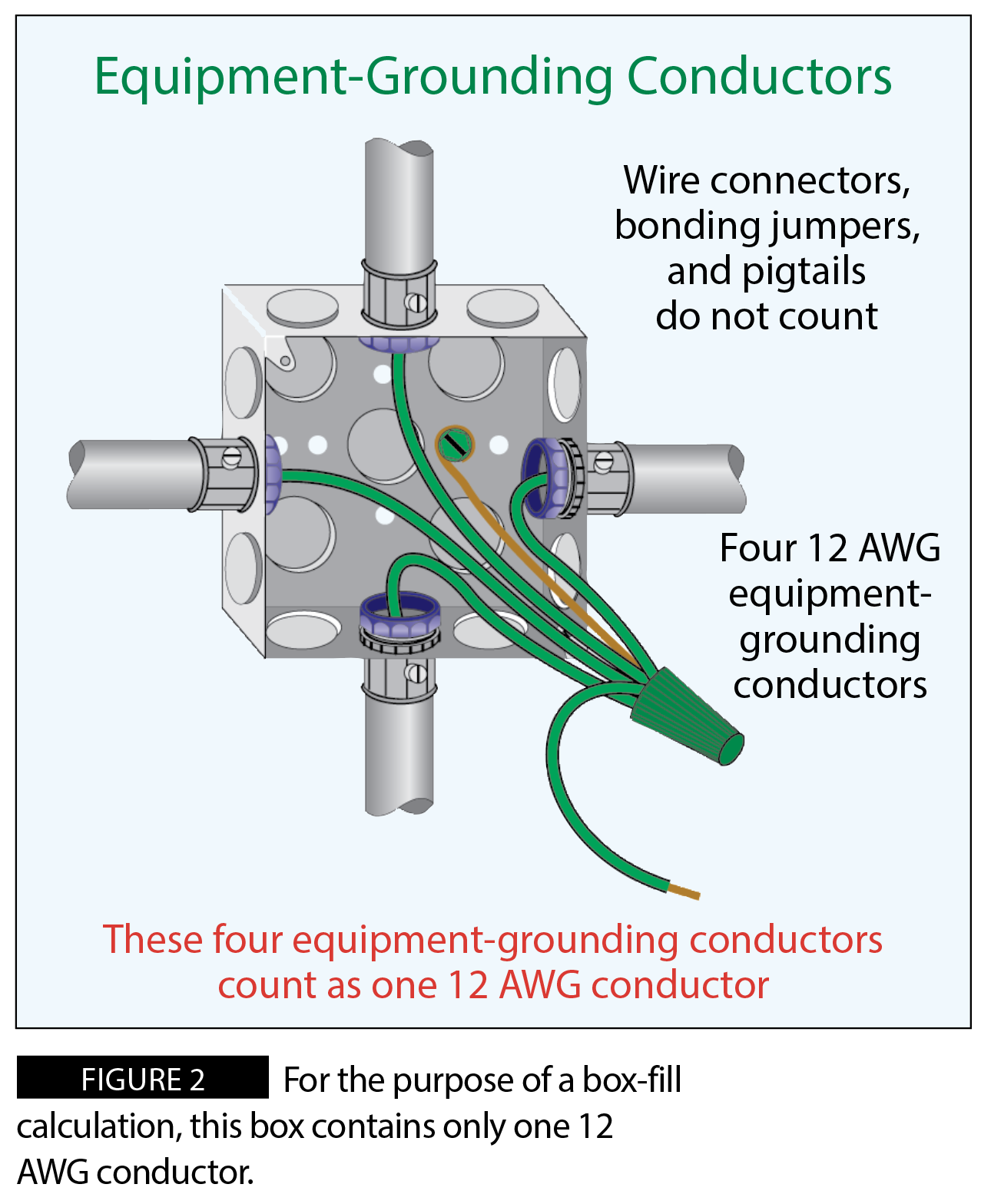
Even if the total number of equipment-grounding conductors or equipment-bonding conductors entering the box is more than two, they only count as one. For example, a box contains four 12 AWG equipment-grounding conductors. When calculating the numbers of conductors or volume allowances, the four equipment-grounding conductors count as one 12 AWG conductor (see Figure 2).
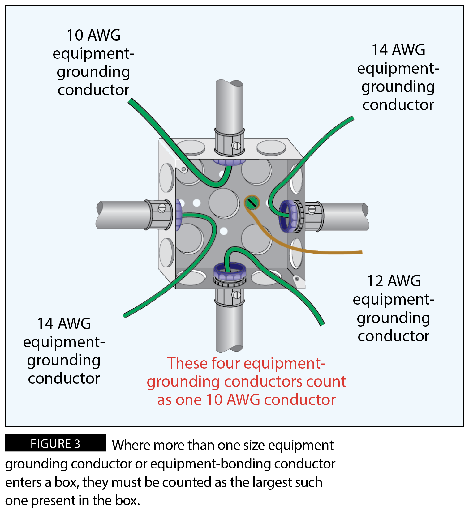
Where more than one size equipment-grounding conductor or equipment-bonding conductor enters a box, they must be counted as the largest equipment-grounding conductor or equipment-bonding conductor present in the box. For example, a box contains two 14 AWG equipment-grounding conductors, one 12 AWG equipment-grounding conductor, and one 10 AWG equipment-grounding conductor. Since the largest equipment-grounding conductor is a 10 AWG conductor, the four equipment-grounding conductors within this box count as one 10 AWG conductor. (See Figure 3.)
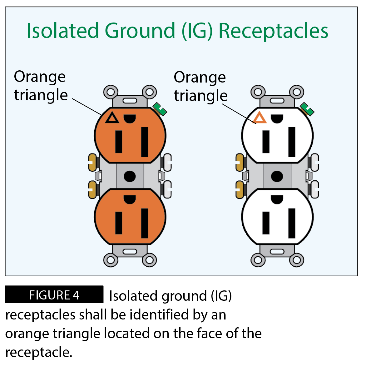
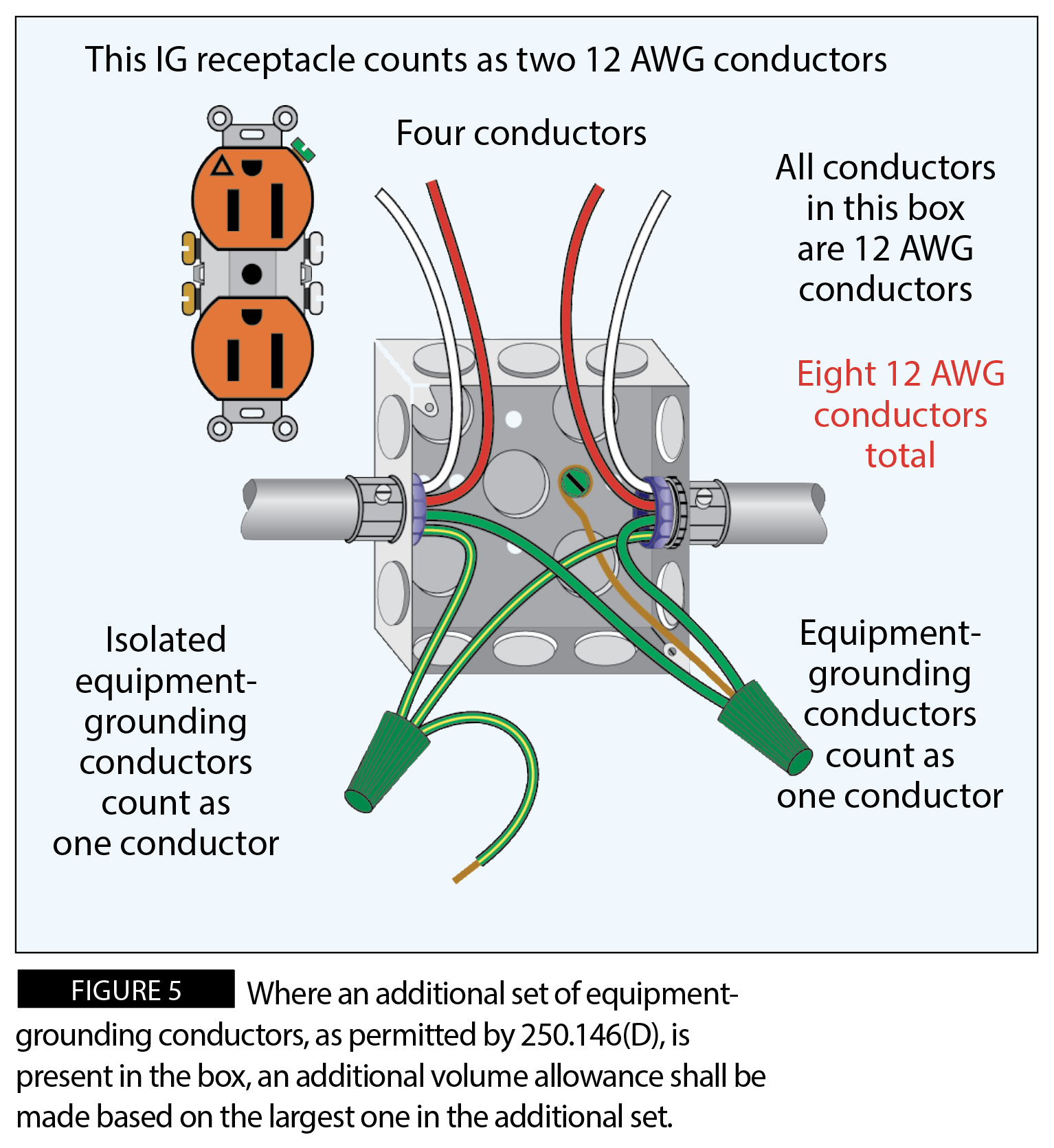
Where an additional set of equipment-grounding conductors, as permitted by 250.146(D), is present in the box, an additional volume allowance shall be made based on the largest equipment-grounding conductor in the additional set. [314.16(B)(5)] The equipment-grounding conductors in 250.146(D) are typically referred to as isolated equipment-grounding conductors. Isolated equipment-grounding conductors are permitted if a reduction of electrical noise (electromagnetic interference) on the grounding circuit is required. With regular receptacles, the grounding terminals and the mounting straps are bonded together. With isolated ground (IG) receptacles, there is no continuity between the grounding terminals and the mounting strap. The grounding contacts and grounding termination in the IG receptacle are isolated or insulated from the mounting strap or yoke. Prior to the 1996 NEC, IG receptacles could be identified by an orange color or an orange triangle located on the face of the receptacle. Now, in accordance with 406.2(D), IG receptacles can only be identified by an orange triangle located on the face of the receptacle (see Figure 4).
As stipulated by the fine print note under 250.146(D), the use of an isolated equipment-grounding conductor does not relieve the requirement for grounding the raceway system and outlet box. Where a box contains one or more equipment-grounding conductors or equipment-bonding jumpers, they must be counted as one conductor. Where the same box contains one or more isolated equipment-grounding conductors, they must be counted as another conductor. For example, and isolated grounding receptacle is needed to reduce electromagnetic interference. Terminating into a four-inch square metal box are two 1/2-inch EMT raceways. Each raceway contains four 12 AWG conductors: one red, one white, one green, and one green with a yellow stripe. A bonding jumper will be installed between the green equipment-grounding conductors and the metal box. A pigtail will be installed between the green with the yellow stripe conductors (isolated equipment-grounding conductors) and the grounding terminal on the isolated ground receptacle. The two red and two white conductors count as four 12 AWG conductors. The two equipment-grounding conductors count as one 12 AWG conductor. The two isolated equipment-grounding conductors count as another 12 AWG conductor. The IG receptacle counts as two 12 AWG conductors. Since the pigtail and bonding jumper are not counted, eight 12 AWG conductors must be counted within this box (see Figure 5).
<< Read Part VII | Read Part IX >>
About The Author
Charles R. Miller, owner of Lighthouse Educational Services, teaches custom-tailored seminars on the National Electrical Code and NFPA 70E. He is the author of “Illustrated Guide to the National Electrical Code” and “Electrician's Exam Prep Manual.” He can be reached at 615.333.3336 and [email protected]. Connect with him on LinkedIn.


