Calibration means that an instrument has been tested against a standard and set up to make measurements traceable to that standard. Within the limits of instrument and measurement uncertainty, your instrument should measure with the same value as the
standard and every other instrument calibrated to that standard.
Fiber optic power meter calibration
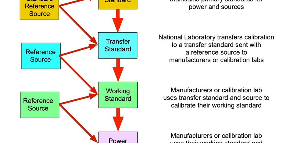
Fiber optic power meters measure optical power and convert the measurement to decibels (dB). The calibration of the instrument is for absolute optical power expressed in dBm, or decibels referenced to 1 milliwatt of optical power. National standards laboratories have special standards called primary standards for optical power, just like they have standards for length, weight or mass and time. There is a process to transfer their primary standards to the instruments you purchase and use in your work.
Fiber optic power meters should be calibrated to transfer standards provided by national standards laboratories such as the National Institute of Standards and Technology. These national laboratories have primary standards used for calibration of optical power at the standard fiber optic wavelengths, 850 nm, 1,300 nm and 1,550 nm. These standards are extremely stable and continuously monitored.
Standards labs create transfer standards consisting of a calibrated laboratory power meter and three laser sources at the proper wavelength that are shipped around to test equipment manufacturers and calibration labs.
The manufacturer or calibration lab calibrates its working standards to these transfer standards and then uses its working standards to calibrate instruments for the customers. When it calibrates a fiber optic power meter, it should place a seal on the
meter indicating when it was calibrated.
A properly calibrated fiber optic power meter will have a typical measurement uncertainty of about ±5% or ±0.2 dB when measuring absolute power. This uncertainty is caused by the limitations of the calibration and measurement process.
Meters should be recalibrated according to the manufacturer’s directions by labs with traceable calibration systems. Many standards call for meter calibration annually to ensure accurate measurements.
Inexpensive meters that offer the option for the user to calibrate the meter themselves should not generally be trusted to measure absolute power, only relative power like loss in dB.
OTDR calibration
One issue you rarely hear about is OTDR calibration, probably because it is, like the instrument, complex. OTDRs measure optical power and time and then convert those measurements into dB loss and distance.
OTDRs do not measure absolute optical power like a power meter, only relative power converted to dB loss. Calibrating the loss scale is a matter of checking the linearity of the power measurement against a calibrated optical power meter, e.g., does the
instrument indicate 1 dB loss when the power drops by 1 dB? This calibration must cover the entire dynamic range of the OTDR, which can be 40 dB or more.
The OTDR distance scale is a bit more complex. OTDRs measure time for the backscattered test pulse returning to the instrument then convert that to distance using the speed of light in the fiber. The distance measurements depend on the accuracy of the
instrument’s measurement of time and the speed of light in the particular fiber, indicated by the effective index of refraction of the fiber. The relationship is:
Speed of light in the fiber = speed of light in a vacuum/index of refraction of the fiber
Since the speed of light in a fiber varies among fiber types and manufacturers, the OTDR allows the user to set the index of refraction. Thus, it is really the time measurement of the OTDR that needs checking and calibration.
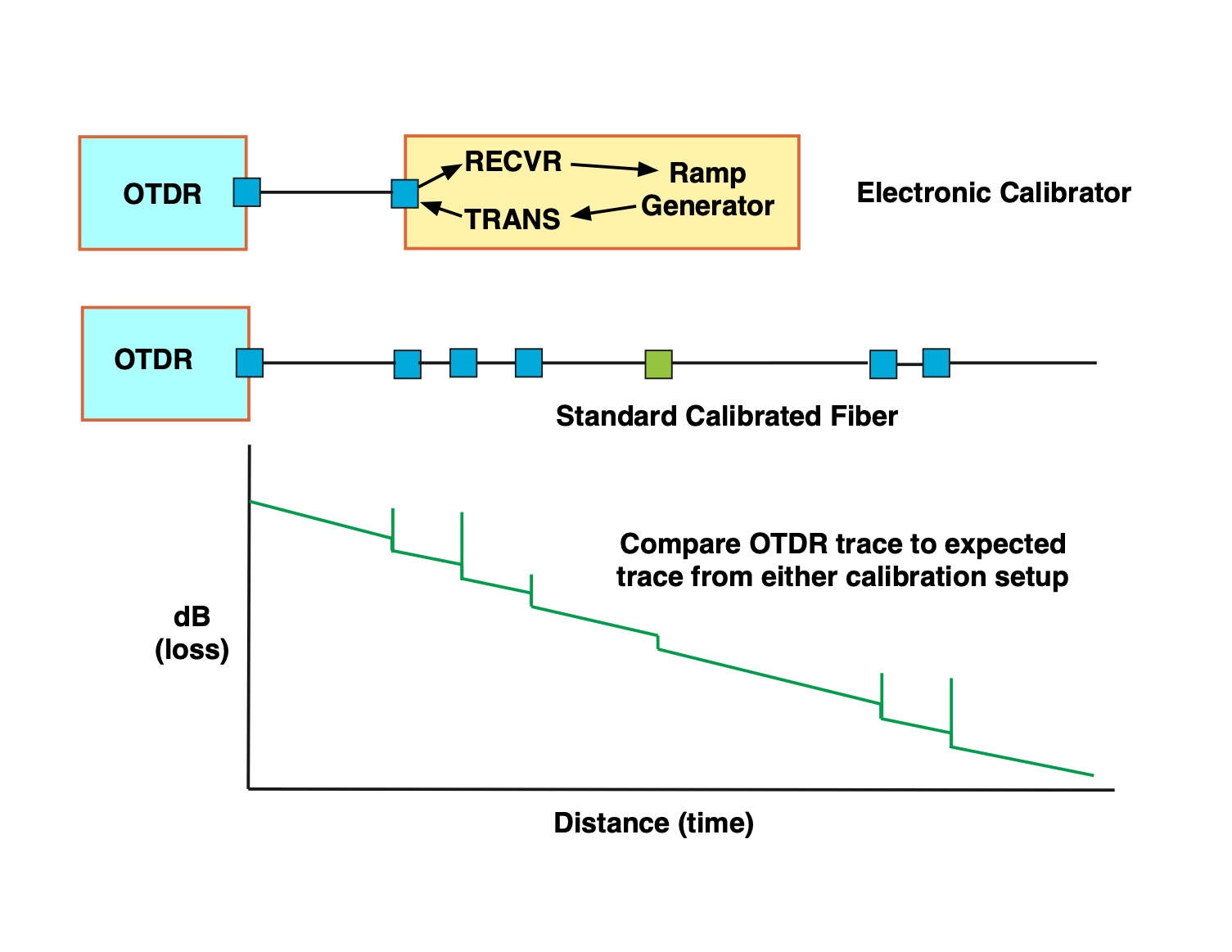
The debate over OTDR calibration has always been whether to use a “standard fiber” method of calibration that involved calibrating every OTDR to read the trace of the standard fiber identically or an electronic method of calibrating the OTDR
time and power measurement that did not involve fiber at all.
National standards laboratories considered the options for OTDR calibration in the 1980s. They first considered making a transfer standard—a “standard fiber”—a sample fiber of known index of refraction and length with splices and
connectors of known loss. This project was never completed as it would require manufacturing many different “standard fibers,” and the method was not agreeable to all interested parties.
An alternate proposal was an external source calibration based on a device that would simulate the return signal that creates the trace. That involves an instrument that would be triggered by the OTDR test pulse and would then generate an optical power output declining over time to simulate the OTDR trace.
 Neither method
gained widespread acceptance. Standards have been written, however. IEC 61746-1 provides a standard for single-mode OTDR calibration using both methods, and TIA/EIA-455-226 is a TIA adoption of the IEC document. This standard offers the two methods
noted above plus an obscure third method based on fiber optic delay lines.
Neither method
gained widespread acceptance. Standards have been written, however. IEC 61746-1 provides a standard for single-mode OTDR calibration using both methods, and TIA/EIA-455-226 is a TIA adoption of the IEC document. This standard offers the two methods
noted above plus an obscure third method based on fiber optic delay lines.
Since there is no readily available standard fiber or source calibrator, perhaps the best method of “calibrating” the instrument is sending it back to the manufacturer to test the time base and receiver linearity and confirm their performance. And, of course, they can do all the other updates, especially software, for the given model of OTDR.
Illustrations by Jim Hayes
About The Author

HAYES is a VDV writer and educator and the president of the Fiber Optic Association. Find him at www.JimHayes.com.


