In my August column, I covered the basics of how each cable has a resistive, inductive and capacitive component. This is generally true about every load and generator. We are only discussing conducted phenomena, which means wires are involved. All conducted PQ phenomena are influenced by these values. In some situations, the values are dynamic, changing with current levels, distribution circuits are rerouted and equipment is switched on or off.
Unless it is a superconductor at absolute zero (–459.67°F or −273.15°C), every conductor has resistance. Ohm’s Law says that current multiplied by resistance equals voltage. The generated voltage is reduced by voltage drops on the way to the load. If the sum of voltage drops is large enough for a short duration, a voltage sag results. A continuous drop is classified as a long-duration undervoltage. Interruptions or outages are usually caused by a disconnection between the source voltage and the load, which is a different phenomenon.
Impedance
When the resistance, capacitance and inductance of a cable or load are combined together mathematically into a single valve, this is referred to as impedance. (Technically, it is two values, magnitude and phase, but we’ll ignore that for now.) The resistance part acts as described above. But the inductance and capacitance act differently and somewhat opposite of each other. The impedance for them depends on the frequency or frequencies of the signal, going up for inductors and getting lower for capacitors as the frequency increases. Signals with a significant harmonic spectrum and transients make the characteristics and calculations a bit complex.
With cables, there are equivalent resistors in series with inductors in each wire or conductor, along with capacitors between each wire. Their valves depend on cable type and materials and conductor diameter/spacing/placement.
In a single-phase circuit, it is typically assumed that the current that goes down the line conductor to the load comes back through the neutral conductor. It doesn’t work exactly that way anymore, because the current harmonics and EMI/RFI filters, surge protection and maybe harmonic filters are built in to the load equipment. More losses in the filters leave less energy for the loads.
When a lightning strike couples energy into the circuit, a portion of that energy eventually goes to the load. The good news is that lightning is a high-frequency transient. Capacitors at high frequencies have much lower impedance and don’t like instantaneous voltage changes—they divert that energy away from going further downstream to the load, but the current increases.
The cable’s inductive component doesn’t like instantaneous current changes, so it also acts to reduce the lightning strike’s impacts. You can generally tell how far away the strike was from the PQ monitor by the attenuation of the energy by the cable length.
Electric utilities and industrial facilities use power factor correction capacitors to compensate the loads’ large inductive component. Inductors cause the phase angle between the voltage and current to be “lagging,” where the sine wave of the current lags in time with the voltage sine wave. Capacitors cause a leading power factor, where the current waveform leads the voltage waveform. In a properly designed and operating system, these two cancel each other out and the voltage and current are back in phase with each other.
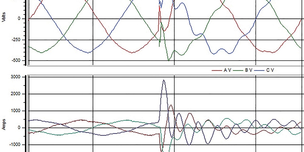
When the cap banks are switched in, they are typically at 0V. The result is the classic PF cap switching transient waveform, as seen above. Unless the cap bank is switched in using a zero-crossing mechanism, the voltage will reduce significantly at first with the current increasing proportionally. The inductance in the wiring says you can’t change the current that fast, so now the voltage swells back up to a value even higher than the original sine wave. It goes back and forth, decaying over 1–3 cycles due to the resistance in the wires. A typical PF cap transient can have a peak voltage transient 1.2–2 times larger than the normal peak, with an oscillation frequency of 300–1,600 Hertz.
An electric motor changes its impedance profile when energized and as it progresses to steady-state. Initially, it has a very low impedance, almost like a short circuit. A large amount of inrush current is supplied through the source impedance, creating a significant, instant voltage drop in the wiring, transformers, etc. The resultant voltage at the motor may be 10%–40% lower, depending on the motor’s size. The unique part of this type of sag is that the voltage recovery follows an exponential curve back to a level lower than before, due to the motor’s steady-state current, which may take cycles or seconds. It’s another easily recognizable VRMS and waveform signature.
Recognizing the effect of impedance on voltage and current from changes in generation/transmission/distribution and loads can help determine the cause and ascertain whether the data recorded by the PQ monitor is real or an artifact of something else. Remember, if the data tries to disprove Ohm’s and Kirchhoff’s laws, look more closely.
Header image by Richard P. Bingham.About The Author

BINGHAM, a contributing editor for power quality, can be reached at 908.499.5321.