Understanding the importance of power quality
Power quality measures how well a power supply system performs to its designed specifications. Historically, power supply problems were often thought to happen in the provider’s distribution system, but a primary cause of these issues is a result of changes in the ways the power is used.
Supraharmonics and standards
As more applications relating to power quality appear, it seems likely that more specialized additional functionality may be required, and not just electrical installation testing, said Frank Healy, product manager at Fluke Corp., Everett, Wash.
“An example would be what are described as supraharmonics. These are very high-frequency harmonics in the range 9 kilohertz (kHz) to 150 kHz, and power utilities in particular are very concerned about inverter inputs of these high frequencies being injected into their network, as they could potentially disrupt the network and cut off hundreds of thousands of customers,” he said. “Other areas relate to the evolving standards around the disrupting equipment. In order to reduce the effects caused, standards are likely to come in place to avoid disruption at high voltage.”
Harmonics, deviations and emerging disruptions
Technicians are now seeing much higher harmonics than the standard 50 they used to measure for. Up to 100 harmonics are now measured, and for some applications, we measure from 2–9 kHz and up to 30 kHz. This is due to the effects of network power being fed into the network from inverters powered by solar panels or wind turbines.
With dips and swells, there are more waveform deviations. Although these are typically small effects, there are significant deviations that can disrupt the power system by causing equipment resets and spurious circuit breaker tripping.
The role of PQ testers in today’s electrical industry
“PQ testers now have to consider the evolving ecosystem of electrical installation and ensure that tester and analyzer meet the changing needs of standards like the IEEE519,” Healy said. Compliance with newer standards like IEC61000-4-7 and IEEE 1459 is also crucial, especially when evaluating higher-order harmonics introduced by inverter-based systems. “In the past, this standard only considered current harmonics; this has now changed, so analyzers need to ensure they capture these harmonics while simultaneously meeting the needs of IEC61000-4-7, the standard relating to the correct evaluation of harmonics.”
Measuring techniques and operator safety
It’s still necessary to physically connect metal clips to conductors to measure voltage, he said. Measuring current has become easier due to the newer ergonomically designed flexible current probes. The user must be alert during the connection process and follow the arc flash rules and recommendations applicable for the type of load being operated and follow local site rules.
“Testers and harmonics need to be able to capture the wider range of harmonics and evaluate the many more wave shape deviations to provide users with useful data,” he said.
Choosing the right power quality testers and tools
There are two levels to consider. The simplest is a load study, which is critical when installing new loads. The default for many users is to run power and energy studies according to National Electrical Code 220.87. This is a simple, but foolproof, method that allows electricians to predict what loads may be added safely. Users can choose an instrument that can perform this test easily. If they choose the right one, the manufacturer will provide an application that can convert the measurements into a full report, providing users with a simple yes/no result.
On the other hand, if the user comes across a more complex problem, they will need something more powerful. It’s not necessary to be concerned about more power leading to a more complicated device. With the right user interface, the instrument capturing the data can be simple.
Wireless connectivity and data reporting
“The more difficult part is evaluating the results,” Healy said. “For this, you will need a power application software package that can easily download your data and provide full reports with just a little help from you to choose the best picture.“ These reports help technicians detect early-stage waveform abnormalities and apply predictive maintenance strategies before failures occur.
“Consider the report to be a story that you can share with others about the electrical system and the potential or real problems that exist. More importantly, consider what to do to fix the problem,“ he said. “Remediating the problem before it happens is always the best route and can be done by making regular checks.
“The significant changes in PQ testing are the overall power of the devices to measure the newer effects of power quality, [for which] faster computing is required,” Healy said.
At the same time, manufacturers should try to follow the customer workflow to make it easy for the technician to use the tool effectively, he said. Setup should be streamlined, and powering the instrument must be flexible. Newer testers may be powered from the measurement circuit, making them much easier to use. Viewing the data locally needs to be easy, so the introduction of even larger displays in full color is helpful.
“Finally, connectivity to the instrument should cover as many bases as the user wants. The default should be USB-C (for best download speeds), ethernet, Wi-Fi, Bluetooth and LTE wireless connection for remote access to instruments for data download and setup. This last one is potentially a huge cost saver, not having to roll a truck out just to download data,” Healy said.
Effects of solar power generation on power quality
Jeff Jowett, senior applications engineer at Megger, Dallas, said a significant challenge in testing power quality has come from the expansion of solar generation. This is a less controlled source of power, and more inverters introduce high-frequency harmonics into the electrical system.
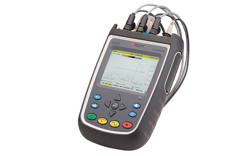
Megger MPQ1000 handheld power quality analyzer
us.megger.com
“Because there are so many potential issues in power quality, there are various tests and measurements that can be made with familiar generic instruments like voltmeters and all-purpose DMMs,” Jowett said. “These can pinpoint and quantize a problem and get you out of a crisis, but a dedicated power quality analyzer is what you really must have.“ Using a comprehensive PQ analyzer helps ensure that power fluctuations, waveform distortion and transient conditions are accurately captured and correlated across systems.
“These instruments are fully featured to identify and quantize all of the potential problems listed above. Equally important, they can be adjusted to tune out factors that you know are not involved with your problem or particular issue,“ Jowett said. “And they also have preventive features that warn the operator of common testing errors like incorrect connections.
“And a full-feature PQ analyzer will provide almost infinite storage space for test data and results that can identify changes that might require routine correction or be the root of a newly seen issue,” he said.
PQ testing techniques and connection methods
PQ meters are connected to the test item by a variety of current clamps and flexible CTs (Rogowski coil), plus banana plugs for voltage input. While many basic types of electrical testing can be performed with simple alligator clips, PQ testing is more complicated and requires knowledgeable operator input. Fortunately, much of this has been anticipated in the tester’s design, and CTs are powered by the unit so that there’s no need for additional connections or batteries. Automatic CT recognition precludes having the unit incorrectly programmed to the wrong range.
“Tests can be started remotely, from within, say, a truck,” Jowett said. “This can provide the operator with an added level of safety when testing in potentially dangerous environments such as where arcing might occur. Having a wireless option can be of help in having access to live data on the PC and taking advantage of real-time data remotely, say within a nearby building rather than having the laptop attached outdoors.” This also enables faster troubleshooting and reduces site visits by allowing technicians to perform remote diagnostics and data extraction.
Solar generation can benefit from PQ testing.
“It is a less controlled source when compared to a utility generator,” he said. “The source of power being the sun, voltages can vary accordingly, and current considerably more. Add to that AC-to-DC conversion. A PQ meter will monitor both the AC and DC sides. Dust buildup on panels also significantly affects performance. Being able to track, record and plot with a PQ meter enables effective and economic cleaning and maintenance schedules.”
Power quality issues: Causes and effects
Jowett said an overview of problems caused by PQ issues should include undervoltages resulting in motor overheating, lights dimming or flashing and manufacturing equipment going offline. Overvoltages damage insulation, break down cable, damage motors and transformers, trip breakers, cause flashovers, take controllers offline and increase current inrush and energy usage.
Sags cause equipment shutdown, switching power supplies operating incorrectly, induction machinery changing speed, reduced output of capacitor banks and dimming lights. Swells can shut down processes, trip breakers, switch relays, cause component failures and affect lighting.
Repeated swells can affect transformers, cable, switchgear and capacitor banks. Transients damage insulation, especially in the first few coils of a motor; damage fluorescent lighting; and cause UPS systems to turn on and off.
Unbalance causes problems for inductive devices and motor overheating. Flicker can negatively affect human visual perception. RVC can negatively affect lighting. Harmonics cause heating and loss of power.
Because there are many PQ tests to be made, it is critical to employ a comprehensive tester that can view the whole electrical system on a level plane rather than trying to analyze suspected issues one at a time with generic instrumentation. Common problems include harmonics, under- and overvoltages, dips, sags and swells, transients, unbalance, flicker and rapid voltage change. These present all-too-familiar issues.
“With a top-quality tester, data can be viewed on a color VGA display, then stored on an SD card. Run out of room? Just use a new SD card. Data can be transferred to PQ analysis software via a USB cable or stick, ethernet or SD card,” Jowett said. “A top quality tester provides record verification and auto CT recognition so the tests designated in setup are not spoiled by incorrect CT connections or incorrect test parameters.”
Looking ahead, Jowett expects oscilloscopes to be added to multifunction testers as a PQ “quick check.” But to monitor PQ effectively without overlooking critical factors, nothing can be substituted for a full-featured PQ meter.
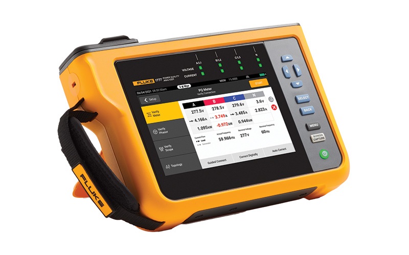
Header image: Fluke 1777 Power Quality Analyzer www.fluke.com
About The Author

GRIFFIN, a construction journalist from Oklahoma City, can be reached at [email protected].