You're reading an older article from ELECTRICAL CONTRACTOR. Some content, such as code-related information, may be outdated. Visit our homepage to view the most up-to-date articles.
They can be useful—but only if used correctly
There are two distinctly different fiber optic applications: premises cabling and outside plant (OSP) cabling. Premises cabling deals primarily with short multimode cables in buildings or between buildings in a campus. Outside plant cables have single-mode fibers and may go for hundreds of kilometers for telephone or CATV systems.
In outside plant fiber optic installations, cables up to 4km long are laid and spliced together to make longer cable runs. The cable’s condition and splice loss must be verified after installation. Restoration can be a big problem in OSP installations. Buried cables are sometimes accidentally dug up during other construction and the location of the fault must be found quickly. The instrument that solves both these testing problems is called an optical time domain reflectometer, or OTDR.
While OTDRs are indispensable in OSP installations, they are less often appropriate in premises cabling installation. They can be very useful in finding installation problems, but only if one understands their operation, limitations and how to interpret the measurement results properly.
How OTDRs work
An optical loss test set (OLTS) measures the loss of the fiber optic cable plant directly using a source and power meter at opposite ends of the cable. The source and meter duplicate the transmitter and receiver of a fiber optic transmission link, so the measurement correlates well with actual system loss.
The OTDR, however, uses backscattered light of the fiber to imply loss. The OTDR works like RADAR, sending a high-power laser light pulse down the fiber and looking for return signals generated by backscattered light from the fiber itself or reflected light from connectors or splices. This indirect method will provide a loss reading for the cable plant, but it will not correlate to the loss of an actual link, due to the different measurement technique. It does, however, contain much useful information on the fibers in the cable plant that can simplify troubleshooting.
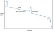
At any point in time, the return signal the OTDR sees is the light scattered from the test pulse passing through a region of the fiber (Figure 1). Since it is possible to calibrate the speed of the pulse as it passes down the fiber, the OTDR can correlate what it sees in backscattered light with an actual location in the fiber. Thus it can create a display of the amount of backscattered light at any point in the fiber (Figure 2).
Since the pulse is attenuated in the fiber as it passes along the fiber and suffers loss in connectors and splices, the amount of power in the test pulse decreases as it passes along the fiber in the cable plant under test. Thus the portion of the light being backscattered will be reduced accordingly, producing a picture of the actual loss occurring in the fiber. Some calculations are necessary to convert this information into a display, since loss occurs twice, once on the test pulse going out from the OTDR and once on the return.
OTDRs can detect problems in the cable caused during installation. If a fiber is broken, it will show up as a fiber much shorter than the cable or a high loss splice at the wrong place. If excessive stress is placed on the cable due to kinking or too tight a bend radius, the loss caused by the stress will look like a splice at the wrong location.
Using an OTDR properly
If you are not properly trained in using an OTDR, you can cause plenty of damage. I have seen untrained installers using OTDRs decide there were major problems in the cable plant when the cable was perfectly fine. In one case, almost $100,000 worth of cable was pulled out in error and the installer bore the cost of the replacement. Never trust OTDR data unless it has been interpreted by an experienced technician, and never—ever—trust the data from the “autotest” feature common on OTDRs without double-checking the data manually.
Test your setup
Whenever using an OTDR (Figure 4), you must always keep a long launch cable attached to the OTDR for measurements. Never attach a cable directly to the OTDR to make measurements, for two reasons: First, the high-power OTDR test pulse overloads the instrument, making measurements close to the OTDR highly inaccurate. Second, you want to check the connector on the cable under test, so you need a reference connector to test it, just like with an optical loss test set.
Before you attach your OTDR launch cable to the cable under test, remove any short patchcords from either end of the cable plant. Most OTDRs cannot resolve cables shorter than 3 to 10m, so patchcords may confuse test results.
OTDRs require setting several test parameters for each cable plant under test. Follow these initial set-up guidelines:
Set the wavelength for initial tests at 850nm on multimode fiber and 1,310nm for single mode. Backscatter is higher at shorter wavelengths, so you can set the OTDR for higher resolution.
Set the test pulse width as short as possible. This gives the best resolution, which helps characterize the cable and locate connectors, splices, etc. You can use a wider pulse if you need to measure longer cables.
Set the distance scale at least two times the estimated length of the cable being tested. OTDRs must show the far end of the cable to produce a true trace of the cable under test.
Set the averaging to a fast setting. The OTDR will make quicker measurements. If the trace is too noisy, more averaging can be used for later traces.
Acquire a trace and examine the results. Manually use the OTDR markers to locate each fiber length and measure its attenuation. Locate each connector or splice and measure its loss. Compare the data to the autotest results to see how well you agree and determine the trustworthiness of the autotest mode.
If the cable plant looks good and the parameters are set properly, acquire another trace at 1,300nm for multimode (1,550nm on single mode) and use the OTDRs comparison facility to compare them (Figure 5). If they look similar, with the exception of the attenuation of the fiber causing different slopes, and the connector losses appear reasonable, the cable is good. The reason to compare traces at both 1300nm and 850nm is the fiber is much more sensitive to stress at 1300nm. If a cable is under stress, it will show much more loss at the stress point at 1,300nm. The OTDR will also show approximately where the stress point is, simplifying rectification of the problem. The same process applies to single-mode fiber, except you test at 1,310 and 1,550nm.
Troubleshooting bad splices and connectors
If a splice or connection is bad, it will show as high loss in the trace. Splices are easy to find and fix, but a connection has two connectors, so how do you tell which one is bad? The easiest way to find out is to take the OTDR to that location and connect the launch cable to each connector in turn to find the combination that is low loss. If a cable tested with high loss with a source and meter, but the OTDR trace looks OK, the culprit is probably the connector on the far end. Take the OTDR to the far end and check it again or attach a long cable to the far end and retest.
Maintaining launch cables
OTDR launch cables are just as important to making good measurements as are the reference cables you use with power meters and sources. The connectors, especially at the end toward the cable under test, must be good to get valid readings of loss at that first connector. Keep this cable clean, inspect the connector regularly and use good mating adapters. Test the connector against a known good connector regularly, preferably using a single-ended loss test with a meter and source.
Measurement errors
As a result of the measurement method, OTDR traces can have confusing features. Short cables can create ghosts from reflections off the ends of the cable, leading the operator to think there are features where none exist. Splices between different fibers can show a gain instead of a loss if the backscatter from the fibers are different. The only way to avoid being confused by these features is to understand the OTDR itself, and that requires study and training. A more comprehensive tutorial on OTDRs can be found at www.LennieLightwave.com. EC
HAYES is a VDV writer and trainer and the president of The Fiber Optic Association. Find him at www.JimHayes.com.
About The Author

HAYES is a VDV writer and educator and the president of the Fiber Optic Association. Find him at www.JimHayes.com.