You're reading an older article from ELECTRICAL CONTRACTOR. Some content, such as code-related information, may be outdated. Visit our homepage to view the most up-to-date articles.
The required test for every installed cable plant is loss or, to be more specific, insertion-loss testing with a light source, power meter, reference cables and mating adapters. Insertion loss is the required test because it checks the cable plant just like it will be used, with a source (just like the link transmitter) that sends light down the fiber to the meter (the link receiver); it measures how much light loss the cable plant causes. The reference cables are used to mate the source and meter to the cable plant under test with matching fibers, measuring the loss of the connectors on each end.
In order to measure loss, one has to establish a reference power level, the “0-dB” reference. Ideally, you use the power meter to measure the output of the launch reference cable at A, what most call a “one-cable reference.” Then the measurement will include the loss at connection A, the loss in the cable plant and the loss at connection B. This method has been the preferred method for most industry standards, such as TIA-568.
Sometimes there’s a problem setting the 0-dB reference and testing this way. The fiber optic connectors on the cable to be tested may not match the connectors on the test instruments.
Over the 30-year history of fiber optics, there have been more than 100 different designs for fiber optic connectors. Fortunately, only a small number have become widely used, such as the ST, SC and LC, the most popular connectors in use today. However, there is a growing usage of multifiber connectors, such as the MT-P, which can connect 12 or 24 fibers at once. There also are some older plug-and-jack style duplex connectors, such as the MT-RJ, still in use.
Since most fiber optic test equipment has inputs and outputs that match either SC or ST connectors, sometimes you need “hybrid” reference cables that have connectors on one end to match the test equipment and connectors on the other end that match the connectors on the cable you want to test. Then, you must find a way to set the 0-dB reference.
If you are using a power meter that has modular connector adapters, you can attach the proper adapter to the meter to mate to the connector on the end of the reference cable. Then you set your reference at the end of the launch reference cable, attach a “receive” reference cable and make your measurement. Even if you have to change adapters after setting the reference, the meters capture all the light, and the calibration will not be affected by the adapter change.
The one time you can easily test different connectors without using hybrid cables is when testing any of the three connectors that use the standard 2.5 mm ferrule: the ST, SC and (practically obsolete) FC. Since they use the same ferrule with different locking mechanisms (bayonet, snap-in and screw-on respectively), they can be mated using hybrid-mating adapters. Thus, a set of ST or SC reference cables that match the test equipment can be used to check all three of these connector types.
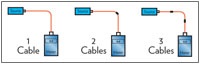
But what do you do when the connectors and test equipment are not compatible? Recognizing this problem years ago, standard testing procedures offered two additional options. The first method can be used if you are dealing with simplex connectors, such as the LC. You set your 0-dB reference by mating the launch and receive reference cables (mating A and B in the diagram above) for a “2-cable reference.” Then, you connect the reference cables to the cable being tested as shown and measure the loss. However, the loss you measure will be less than the loss measured by the one-cable method, since there was one connection loss between the two reference cables when the reference was set.
If the connectors are plug-and-jack-style connectors, it’s more complex. These types of connectors are generally installed with jacks on each end, which requires reference cables with plugs on each end, which cannot be mated to set a reference. The only recourse is a “three-cable reference” where a short piece of the same type of cable is inserted between the reference cables, and the 0-dB reference is set. When the cable is tested, the loss will be lower by the loss in both connections included in the reference measurement.
International standards recognize all three methods. The one-cable reference, also called Method B, is the preferred method, but as long as the test result documentation includes the method used, any of the methods is acceptable.
HAYES is a VDV writer and educator and the president of The Fiber Optic Association. Find him at www.jimhayes.com.
About The Author

HAYES is a VDV writer and educator and the president of the Fiber Optic Association. Find him at www.JimHayes.com.


