You're reading an older article from ELECTRICAL CONTRACTOR. Some content, such as code-related information, may be outdated. Visit our homepage to view the most up-to-date articles.
When one of the coaches was asked before the “big game” what would be the key to his team’s success, he said, “executing the fundamentals.” While blocking, tackling, passing and catching may work for football, Ohm’s and Kirchhoff’s Laws are fundamental to understanding any power quality issue. While trying to explain some data from a power quality monitor to a utility engineer and then trying to explain the concepts of electricity to an apprentice at a heating, ventilating and air conditioning (HVAC) school, I decided there might be a need for something even more basic, more fundamental, that needs to serve as the basis for power quality discussions. To do so, we will shift from the electrical domain to the mechanical domain or, more accurately, fluid mechanics, as shown in Figure 1.
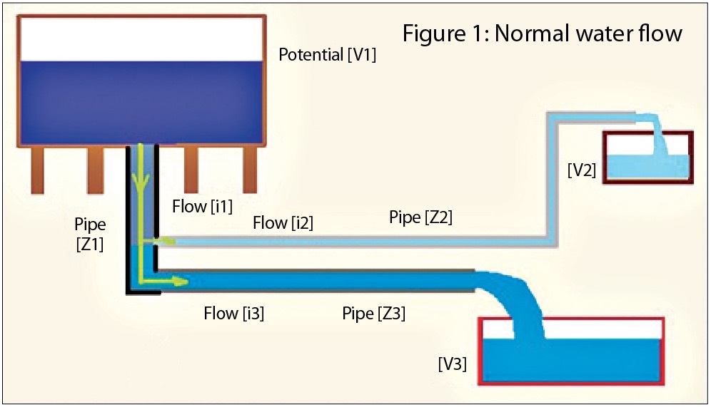
A water system consists of a tank or reservoir that has a certain amount of potential (V1) to move amounts of water (V2 and V3) for use at other locations. Even if the water is not flowing (i1) from the source, it still has the potential to work or move by nature of the volume and height at which it is stored. When the valve is open and water flows, the laws of fluid mechanics govern the rate and amount that flows. The larger the pipe (Z1 Z3 Z2), the more water can flow at a faster rate for the same amount of potential V1. The smaller diameter pipe is like having a higher impedance in an electrical circuit. So V3 will fill up with more water and faster than at V2. Like Kirchhoff’s Law, the water flow leaving tank i1 will equal the flow in i2 plus i3. Eventually, the original amount of water at V1 will equal the sum of water at V2 and V3.
Kirchhoff’s Law states that the sum of currents leaving a node must equal zero. In other words, what goes in must equal what goes out. For voltage, the sum of the voltage around a closed loop must also equal zero.
Ohm’s Law states that the voltage equals the current multiplied by the impedance (resistance in a circuit without any inductance or capacitance); or, rearranging terms, the current equals the voltage divided by the impedance. This is the case with our fluid example, hence the subtle choice of using V, I and Z. (That normally lowercase “i” represents instantaneous current, but it is used here to prevent confusion with the number 1.)
The same fluid example can be modified to simulate a power quality disturbance, as shown in Figure 2. Things are going along normally when a hole breaks in Z2, resulting in water flowing out as Flow i4. The sum of all of the flows will still be a net zero, and the sum of V2 + V3 + V4 will equal V1. However, V2 will not be equal to the same amount as in Figure 1 prior to the break. V3 will see a slight drop in its volume but not as severe as if the hole had developed in Pipe Z3.
This is similar to what happens on parallel feeders or circuits when a significant amount of additional current flows on one of the circuits, either through large load starting up or a fault condition. As a result, the voltage will be reduced, i.e., a sag. If the hole were large enough, all of the water would be diverted away from V2, resulting in an “interruption” in the water supply. If V1 is enough potential and the size of the Pipe Z1 is so much larger than Z2, then there will be little effect on Flow i3 and the resulting water in V3. This would be like having a very “stiff” electrical source with very little source impedance. If not the case, then Flow i3 will also suffer a reduction in rate and less water to V3.
Though the pipe or circuit impedance before was considered to just be a resistive element, a capacitor and inductor could also be modeled in the fluid system. A capacitor doesn’t like to have its voltage changed instantaneously. It acts as a short-term storage device. This could be a small water-storage component of the system. If it was downstream from where the break occurred, it could provide a short-term supply of additional water to keep Flow i2 the same amount of water going into V2.
An inductor doesn’t like to have its current or flow rate changed instantaneously either. This could be analogous to a pump with a small gasoline tank in series with the pipe or circuit. When the pipe break causes a drop in pressure, an upstream pump could kick in and draw more water from the main flow than would normally occur from the pressure of the water tank until gas ran out.
This alternative model helped the HVAC apprentice understand the concepts better. The utility person wasn’t impressed and still wanted to know what caused the transient recorded by his monitor.
About The Author

BINGHAM, a contributing editor for power quality, can be reached at 908.499.5321.


