You're reading an older article from ELECTRICAL CONTRACTOR. Some content, such as code-related information, may be outdated. Visit our homepage to view the most up-to-date articles.
Insulation testers are instruments every electrician should have in the tool bag. They are handy for routine maintenance where they can be used for pass/fail testing and for troubleshooting, but they really come into their own for predictive maintenance (PdM). Good insulation testers (as well as infrared temperature guns) are ideal for spotting a failure that’s on the way, which is better than waiting to analyze what happened after the fault.
There are basically two types of insulation testers: insulation resistance and high potential (hipot). Both can be used for predictive maintenance and pass/fail testing, but the insulation resistance type is easier to carry and generally won’t harm the insulation. Insulation resistance is tested at voltages lower than the component’s voltage rating. Hipots, on the other hand, are generally used as a proof test at voltages above the component’s rating. They have to be used carefully, for example, by applying the voltage in steps and using sensitive overcurrent trip circuits to prevent the insulation from failing as a result of the test.
Insulation resistance
Since insulation is not a conductor, its resistance should be infinite. That’s the way we were taught to treat it in school, but in the real world, a perfect insulator does not exist. The resistance of an insulator only has to be high enough that the amount of current it draws is insignificant compared to the conductor it is protecting.
Insulation resistance testers work basically like the resistance ranges on your standard multimeter; they have a built-in voltage source, the voltage is applied to the component you are measuring, and the meter reads the resulting current. The meter is calibrated to display ohms instead of amps. It does that by using Ohm’s Law: Resistance = volts/amps.
What makes the insulation resistance meter different is that it is designed to measure the (hopefully) very high resistance of an insulator, which can range from hundreds of megohms (106), to gigohms (109) and even up to terohms (1012). In order to get a reasonable current flow through these resistance ranges, you must use increasingly higher voltages. For example, 1 microamp at 100 megohms requires a source of 100 volts (V); at 1 gigohm, it requires 1,000V. Typical handheld insulation resistance testers go up to 1,000V, so for them to read resistance above 1 gigohm, the testers must have very good sensitivity, i.e., be able to read currents well under 1 microamp.
Here the question is whether you are just doing a pass/fail test or gathering data for a preventive maintenance log. For pass/fail, it’s good enough to apply the test voltage and see that the meter reads at the top of its range. For PdM data, you need a sensitive instrument with a stable voltage source.
Think about your goals when you are selecting a test instrument—there can be a significant price difference. A handheld meter with a 1,000V source should be just right for troubleshooting typical building wiring rated at up to 480V. For industrial installations where there might be standard 4,160- or 2,400V wiring, you would need an instrument with a 5,000V source. Although it could still be portable, you won’t find it in a multimeter-type handheld case.
Troubleshooting
A quick insulation test can be very useful to an electrician after installing new wiring and before power is applied. A basic handheld meter is just right for that kind of application.
“Basic units just look at whether the insulation is good enough,” said Jeff Jowett, senior application engineer, Megger Inc., Dallas. “Was something defectively installed or did someone run a drill through the insulation? There, you don’t need a whole lot of range, you just need to know you’ve got a gig or two of resistance. That’s enough to tell you there wasn’t any damage,” Jowett said.
A standard, handheld multimeter can typically measure up to a maximum of 60 megohms, so you need an insulation tester to reach the gigohm level.
For example, the Megger MIT 400 series are handheld 1-kilovolt (kV) meters that read to 20, 100 or 200 gigohms, depending on the model, and they can measure voltage and normal resistance as well.
Fluke Corp., Everett, Wash., offers a full-featured, handheld multimeter, the model 1587, which can make insulation resistance readings up to 2 gigohms in addition to a full array of multimeter features. The company’s handheld 1503/1507 insulation testers can measure up to 10 gigohms.
Waltham, Mass.-based Extech Instruments Corp.’s handheld model 380363 goes up to 10 gigohms, while the company’s analog model 380320 measures to 400 megohms.
Predictive maintenance
For PdM, you need more sophisticated instruments and software. According to industry expert Jim Phillips (www.brainfiller.com), “Insulation degradation is one of the main causes of component failure that can result in an outage. Voltage stress, aging and temperature can all lead to such a failure, which can create a short-circuit.”
Setting up a program to measure insulation resistance at regular intervals can enable you to spot degrading insulation before it fails. To use insulation testing for PdM, you need to keep precise records during regular time intervals to identify a trend that indicates insulation is degrading. A component, such as a motor or a run of power cabling, can then be taken offline and repaired or replaced before it fails and takes out other equipment with it.
“For long-term, supportive maintenance, you want numbers to work with, rather than infinity readings like on the old analog meters,” Jowett said. “For example, an installed piece of equipment—say a motor—could be reading in the terohm range, but if the readings are dropping at a fairly sharp rate, that could tell you there’s a potential problem … if, however, it’s operating at a much lower resistance level, but maintaining that for years, your conclusion would be completely different.”
In other words, you would need good, reliable data.
Another scenario, however, might be in a large chemical processing plant with thousands of motors running critical operations, such as process pumps. If there are many identical motors, the maintenance crew will have a pretty good idea of what the readings should be. So the crew might set a pass/fail threshold level and, say, if the insulation drops any lower, the technicians could pull and repair the motor.
In both cases, you need solid and reliable data. Since the currents being measured are so small—in the nanoamp and picoamp ranges—that can be tricky. Diagnostic testing can sometimes require insulation test sets that go up to 5 or 10 kV, beyond the range of handhelds. It depends on the insulation resistance of the material under test.
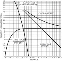
Now, to set up a good database for your PdM program, you must consider a number of important factors. The first thing is to understand that the total current in insulation is actually made up of three components: capacitance charging current, absorption current and leakage current.
Generally speaking, high leakage current tells you something is wrong, so it is important to be able to know which portion of your reading is due to leakage current rather than being the result of the two other components.
Another problem is that leakage current varies with ambient temperature. For example, according to Phillips, “A generally accepted industry rule of thumb is that for every 10°C, the leakage current doubles, which means the resistance is halved.”
In collecting data, it is important to note the ambient temperature, so you can apply a correction factor when comparing readings. If the ambient temperature falls below the dew point—the temperature at which moisture in the air condenses—condensation can form in small cracks, which voids and affects the leakage current and resistance readings.
Practical techniques for diagnostic insulation testing
It is more difficult to deal with humidity. One option is to use a test method that discounts environmental factors. The polarization index (PI) is a test method designed to do just that.
Capacitance charging current occurs because all insulators act like capacitors, but because their capacitance value is generally very small, the charging current decays in a short time—well under a minute.
Absorption current has to do with molecules within the insulation aligning with the electricity field set up when high voltage is applied.
The PI test is designed to provide a method for dealing with all of these factors. It is actually very simple to perform, as long as you have good quality insulation resistance test equipment. Simply record the insulation resistance reading one minute after the test voltage is applied and then again 10 minutes after it is applied. The PI is defined as the ratio of the 10-minute resistance reading to the 1-minute reading (PI = 10-minute reading/1-minute reading).
The PI should be greater than 1 because currents due to capacitance charging, absorption and condensation should be greatly reduced after 10 minutes; therefore, the insulation resistance reading should be noticeably higher. IEEE Standard 43-2000, “Recommended Practice for Testing Insulation Resistance of Rotating Machinery,” provides acceptable values. Minimum values in the standard are 1.5 or 2.0, depending on the type of machine, but higher values are preferable; five would be excellent. The theory underlying this test makes the reasonable assumption that both readings were taken under similar conditions of temperature and humidity. PI is, therefore, an excellent number to use for keeping a history on a piece of equipment.
Safety
It should go without saying that when you are doing high--voltage testing of any type, you must take great care to do it safely. Read and adhere to the procedures and warnings in the tester’s instruction manual. Always perform insulation testing when the circuit is de-energized. Disconnect any sensitive equipment that could be damaged by high voltage.
Insulation resistance and hipot testing can be a valuable tool, but it must be used with care and understanding.
BROWN is an electrical engineer, technical writer and editor. For many years, he designed high-power electronics systems for industry, research laboratories and government. Reach him at [email protected] or at www.writingengineer.com, an independent professional writing service.