You're reading an older article from ELECTRICAL CONTRACTOR. Some content, such as code-related information, may be outdated. Visit our homepage to view the most up-to-date articles.
Many of the problems encountered in troubleshooting fiber optic networks are related to making proper connections. Since the light used in fiber optic systems is infrared (IR) light, which is beyond the range of the human eye, one cannot see it. By injecting the light from a visible light source, one can visually trace the fiber from transmitter to receiver to ensure correct orientation and check continuity. The two simple inexpensive instruments that inject visible light are called fiber tracers or visual fault locators.
Fiber optic tracer
The fiber optic tracer is a low-power, visible lighting source for multimode optical fiber. It uses a bright incandescent or visible light-emitting diode source to inject enough light into the fiber to allow visual tracing of fibers and to perform continuity checks. With the low power output of the fiber optic tracer, there is no danger to the eye, but the eye is so sensitive these devices can be used to trace multimode fibers up to several kilometers (more than a mile) long. Most tracers accommodate standard fiber optic connectors or can be used to check unterminated fibers with a bare fiber adapter.
Continuity testing
Continuity testing is useful to check a few fibers in a cable on the reel before installation or in a terminated cable to determine if it has been damaged. To test for continuity, attach the fiber to the fiber optic tracer using a bare fiber adapter or unterminated connector and see if light is visible at the far end.
One of the best uses for these devices is to trace fibers for identification or to determine correct connections, which can be especially important if good documentation is not available. To trace fibers using the fiber optic tracer or visual fault locator (VFL), connect the fiber to the output connector of the tracer. The light output will be visible to the eye at the other end of the fiber. This allows identifying fibers in multifiber cables to be tested for insertion loss or for making proper connections during installation.
If a powerful visible light from a red diode laser is injected into the fiber, not only can fibers be traced but high loss points can be made visible. Most applications center on short cables to connect to the fiber optic trunk cables, such as those used in premises cabling or telco central offices. The VFL works best on short cables, up to a few kilometers (km); thus, it covers the range where optical time-domain reflectometers (OTDRs) are not useful because of the dead zone of the OTDR. The VFL is the perfect complement to the OTDR in cable troubleshooting.
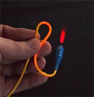
Visual fault location will work on buffered fiber and even simplex cable if the jacket is not opaque to the visible light. The yellow jacket of single-mode fiber and orange of multimode fiber will usually pass the VFL light. Most other cable jacket colors, especially black and gray, will not work with this technique. However, many cable breaks, macrobending losses caused by kinks in the fiber, bad connectors or patchcords, splices, etc., can be detected visually.
The visible laser cable fault locator also allows optimizing splices and tracing fibers.
It is safe for use, classified as a Class II laser and has power levels low enough to prevent harm to the eyes but powerful enough to trace single-mode fibers for 4 km or more.
Finding faults
The higher power of a VFL can find breaks in fibers or high losses around connectors in simplex cables. The light that escapes at a break, for example, will be visible through the jacket of the cable. This is extremely helpful in finding cable faults near the end of a cable where the dead zone of the OTDR makes it impossible to resolve faults. It also allows finding cracked fibers or bad splices in splice closures where an OTDR cannot resolve faults.
Splices and splice optimization
Optical splices, especially the mechanical type, will often be visible when light from the FOtracer is being transmitted through the fiber. If the splice is close to the connector, such as when a pigtail is spliced to a cable, there is enough light to allow optimizing the splice. Adjust the positioning and/or rotation of the splices until the light from the splice is minimized, indicating maximum transmission or minimum loss.
One or both of these tools should be in every installer’s toolkit. They will find them the most useful tool for fiber optic installations.
HAYES is a VDV writer and educator and the president of The Fiber Optic Association. Find him at www.jimhayes.com.
About The Author

HAYES is a VDV writer and educator and the president of the Fiber Optic Association. Find him at www.JimHayes.com.