This week, two questions posed to me ended with the same explanation.
The first person asked why their newly installed storm door would close and latch just fine when they went into their house, but failed to latch when they departed through the same door.
“It’s just physics,” I commented after doing a demonstration of the trapped air, though I also told them to turn the adjust screw on the door recloser piston to give it more force when closing.
I gave the same response when someone else asked me why their lights kept blinking, especially at night. Voltage sags, referred to in power quality standards as short-duration rms voltage variations, have been the most common type of disturbance in nearly every benchmark PQ survey reported. They have also been the most common source of PQ investigations I’ve conducted. Even the least expensive instruments that claim to record PQ phenomena record voltage sags. The newer lighting technologies aren’t immune to such, but their response is different than incandescent bulbs.
Two categories of phenomena
Power quality standards classify PQ phenomena into two broad categories: radiated and conducted. Radiated phenomena generally require specialized instruments to capture and record them. Some past adapters converted these higher (and much higher) frequency signals into something that some PQ recorders could measure. There was the occasional radio frequency burst from a walkie-talkie getting into unshielded communication cables, and even the report of a faulty vacuum cleaner motor that would disrupt a data center each night when the cleaning crew came through. In general, the occurrences that caused equipment misoperation were very few. (Though if instruments weren’t looking for them, how did we know that there weren’t more such issues?)
Conducted phenomena are carried from the source of the disturbance to the affected equipment by the wires between them. They include transients, sags, swells, interruptions, harmonics, interharmonics, unbalance, frequency variations, flicker and conducted noise. The same rules of physics can generally explain the behavior of all these phenomena.
To fully explain them requires extensive knowledge of physics and mathematics. James Maxwell, a 19th-century physicist and mathematician, gave us equations that completely describe the generation and interrelation of electric and magnetic fields that we call PQ phenomena. Following the unspoken rule of not using partial differential equations in my articles, let’s stick to simpler explanations.
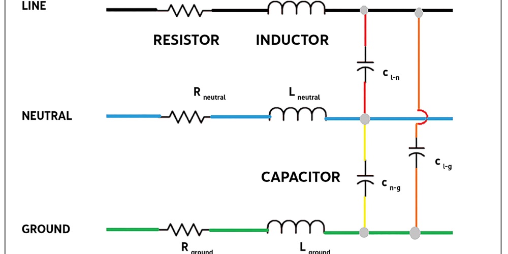
The diagram shows a representation of what happens in a cable used in many commercial and residential circuits. All wires have a resistance, usually denoted as ohms per foot (or mile). Wire also has an inductance value, and between any two wires there is a capacitance value. The same concept applies to cables used in three-phase circuits, including distribution and transmission systems, though the values and interactions are more complex.
Resistors develop a voltage across them proportional to the current going through them. It doesn’t matter if the frequency is DC or 60 hertz AC or 3,000 Hz harmonic. It is still directly proportional (if the resistor is considered an ideal resistor).
Inductors are different. Their impedance depends on the frequency. The higher the signal’s frequency, the higher the impedance. They don’t like the current to change instantaneously, which would be a high-frequency signal as long as the current keeps changing rapidly. When that happens, a much larger equivalent voltage will be developed across them than if the current slowly increased.
Capacitors are the opposite. Their impedance goes down as the frequency of the signal goes up. They don’t like the voltage to change instantaneously. When it does, the current goes up dramatically.
When a resistive load, such as a heater, turns on, the additional current it draws will flow from the source through the line conductor and back through the neutral conductor. The sum of the resistance value of the wires is normally orders of magnitude smaller than the load so that the load current multiplied by the line resistance will produce a small voltage drop. These reduce the source voltage by a small amount at the load.
However, when multiple loads are on at the same time, the voltage drop gets larger, sometimes large enough to be classified as an undervoltage condition, or what used to be referred to as a “brown-out.” If the current level changes very quickly from a load such as a large-horsepower motor, there is resistive-based voltage drop in the wires and the inductance of the wire has a short-duration voltage drop. This leaves even less voltage remaining for the load.
Header image by Richard P. Bingham.
About The Author

BINGHAM, a contributing editor for power quality, can be reached at 908.499.5321.