
In my column in February’s print issue of ELECTRICAL CONTRACTOR, I suggested it was a good time to upgrade your KSAs—your knowledge, skills and abilities—in fiber optics. Online I thought I’d present you with an online self-study program to help you understand one of the most complicated tools used in fiber optics, the optical time domain reflectometer, or OTDR.
In this OTDR Self-Study Lesson Plan, I will give you an introduction to the topics and send you off to read a short article on ECmag.com. If you have an OTDR, I’ll give you some experiments to perform to help you understand it better. Then I’ll give you a short quiz to test your comprehension. Don’t worry, we’re not keeping score, and we’ll give you the right answers so you will learn from the quiz too.
Ready? Let’s go.
In this lesson plan, I assume you are familiar with fiber optic basics and jargon, but here’s a quick refresher course on the FOA website.
What’s An OTDR?
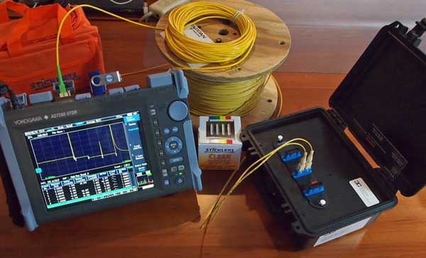
The OTDR is one of the most powerful testing and diagnostic tools available to the fiber optic technician. If you have been around fiber at all, you have heard about them but may not know what they are used for or when they are used.
Lesson 1
What is an OTDR, how does it work and what can it test? Read this article on OTDR basics to freshen up your knowledge.
Experiments With Your Equipment No. 1
If you have an OTDR and some long-ish fiber optic cables, here are some experiments to perform.
- Use connectors and splices to connect the cables.
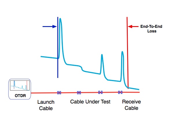
- Create a simulated cable plant with some fiber optic cables long enough to be seen by the OTDR, typically 10-100 meters or more. (It’s called “Cable Under Test” in the drawing above.)
- Connect your OTDR with launch and receive cables to the simulated cable plant.
- Using the automatic test mode of the OTDR take a trace.
- Measure the length of your simulated cable plant, the location of all connections and splices and the end-to-end loss as shown in the article. The OTDR should also give you losses and reflectance for all connections and splices. Save the data on the OTDR memory or write it down.
- Using the manual controls for setup of the OTDR parameters, select the proper wavelength, the shortest range that allows you to test your simulated cable plant, the shortest test pulse and minimal averaging.
- Measure the length of your simulated cable plant and the location of all connections and splices.
- Using manual controls for 2-point losses, set the OTDR markers for each splice or connection and manually measure the loss. Compare this to the data from the autotest done above. Are they different?
Lesson 2
When using an OTDR, it’s important to know how to use a “least squares analysis” to get a more accurate measurement. Read about using “least squares” features on your OTDR.
Experiments With Your Equipment No.2
- Using the same setup as in Lesson 1, measure several connections or splice losses with both 2-point and LSA methods. How close do they agree?
Lesson 3
Understanding OTDR “gainers” is one of the more confusing measurement quirks of all fiber optics. Brush up on gainers in this article.
Experiments With Your Equipment No.3
- Using the same setup as in Lesson 1, measure several connection or splice losses with LSA methods.
- Now reverse the “cable under test” so you can test the same connections or splices in the opposite direction. (Be sure to keep track of the directions so you compare the same connections or splices.) How close do they agree?
Lesson 4
OTDRs can confuse you if you are not watching carefully. Read about OTDR trace anomalies called “ghosts.”
Experiments With Your Equipment No. 4
- Set up your OTDR and launch the cable only.
- Attach a fairly short cable to the launch cable and take a trace.
- Do you see more than one reflection from the connection and the end of the short cable? How do you know those are ghosts?
You’re Done – Good Job!
Now you should have a good understanding of how OTDRs work and how they can make measurements.
Want to test what you have learned? Take this Fiber U quiz.
About The Author

HAYES is a VDV writer and educator and the president of the Fiber Optic Association. Find him at www.JimHayes.com.


