
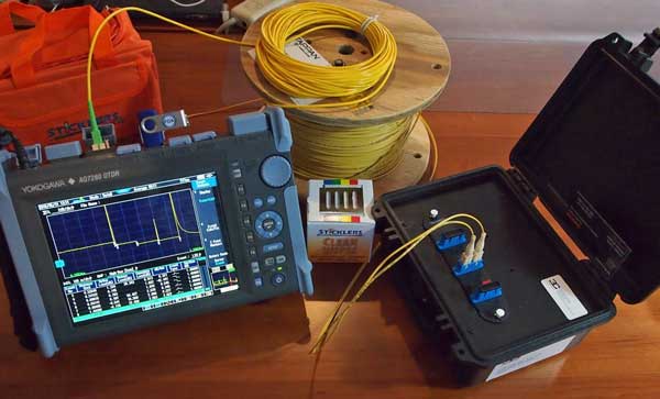
The most powerful—and complicated—instrument used for fiber optic testing is an optical time domain reflectometer (OTDR). In the hands of an educated tech, the OTDR is a powerful testing and troubleshooting tool, but it can be a confusing and unreliable tool if the operator does not understand its proper use. Here is what an OTDR looks like:
Unlike insertion loss testing with a test source and power meter, the OTDR makes an indirect test using a technique often compared to radar. It’s actually better than radar because you don’t only get reflections from objects like airplanes and measure the distance; you also get information from along the path of the signal—sort of like radar that measures the density of the air to the object.
How does an OTDR work?
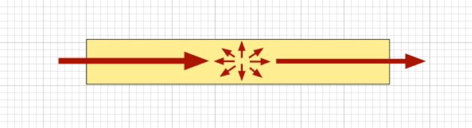
How does that work? The OTDR sends a strong light pulse down the fiber and looks at the signal that comes back to the instrument. As it goes along the fiber, the glass in the fiber attenuates the light. It absorbs some of the light and scatters some light too. The scattered light goes in all directions, including a small amount—about 1 part per million—straight back to the OTDR itself. We call that backscatter.
Calculating signal distance and speed with an OTDR
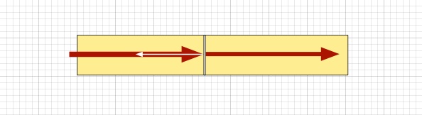
The OTDR captures the backscatter light coming and measures its optical power. Since the backscatter is caused by a pulse in the fiber and we can measure the time from when the pulse was sent down the fiber to when it returns, we can determine the test pulse’s position in the fiber by calculating distance from the time the pulse has been traveling down the fiber multiplied by the speed of light in the fiber, corrected, of course, for the fact that the light has traveled down the fiber to the point we are measuring and then back to the OTDR—double the actual length of the fiber.
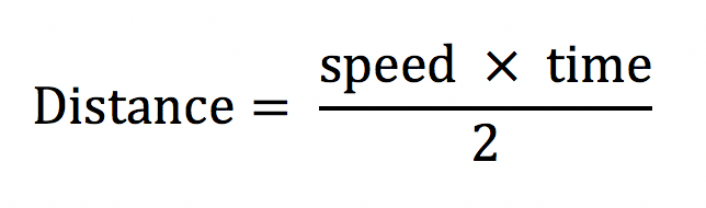

The fiber manufacturer provides the index of refraction for the fiber being tested. Most fibers have an index of refraction of about 1.47, so if you use the equation above, you find light in a fiber travels about two-thirds the speed of light in a vacuum like outer space. If you like trivia, the light travels about 1 meter in 5 nanoseconds (that’s a billionth of a second) or about 8 inches per nanosecond.
Calculating the attenuation coefficient with an OTDR
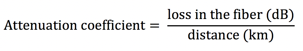
Back to the OTDR. It can measure other things besides distance. It also measures the optical power from the backscattered light. As the test pulse goes down the fiber, it is attenuated on both the outgoing and return paths, causing the signal to decline as the pulse goes farther down the fiber. We can measure the reduction in the power between two points, and it becomes the loss of the fiber over that distance—twice the actual loss because we measure the results of attenuation in both directions. Correcting for that double path enables us to determine the attenuation of the fiber over that distance, so we can calculate the attenuation coefficient of the fiber.
The OTDR also gives us a visual representation of that measurement in a display called a trace:
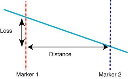
The markers indicate the distance points we use for the measurement, the horizontal scale is distance and the vertical scale is the loss measured in decibels between the markers. Thus, we can have both a digital number and a graphical representation of what the OTDR is measuring.
But wait, there's more! Accounting for splices and connectors
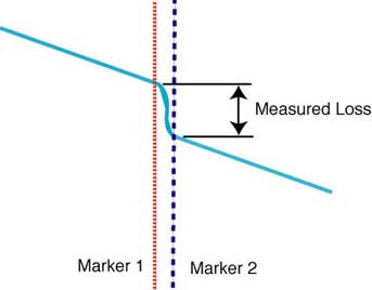
As the OTDR test pulse goes down the fiber, it may pass a joint—a splice or connector. As the pulse passes a joint, it suffers some loss, reducing the power in the signal and the returned power to the OTDR. Just like the loss measurement, the light passes through the joint twice, outgoing and return, so we make the same corrections.
On the OTDR display, we can see the fiber joint and measure its loss. If it’s a splice, it looks like this:
If you look closely at the diagram of loss in a joint, you will see a small white arrow pointing back from the joint. That’s reflectance. At a fusion splice, the two fibers are welded together, becoming essentially one piece of glass, and there is no reflectance. However, every connection has a little bit of air between the two fibers, causing some reflectance. That reflectance is much higher than the backscatter from the fiber—by as much as 30 dB—so you get a spike of light at the connection. It looks like this:
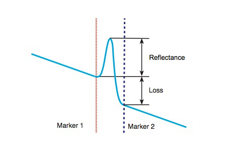
This trace of a connection with the reflectance peak shows how the OTDR can measure both loss and reflectance.
Testing with an OTDR
Combine these test methods, and you can test a complete cable. However, there are a few more things you need to know beforehand.
First, OTDRs don’t work on all cables. They were designed for long cables like those used in in long distance telephone systems. Some modern OTDRs are adapted to shorter cables, so if you are testing cables under about 1 kilometer long, you need a special high-resolution OTDR.
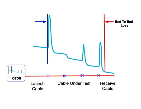
OTDR testing needs reference cables to test the entire cable just like insertion loss testing. The OTDR sends out a powerful test pulse that overloads the instrument for some time. A long launch cable is used to let the OTDR settle down and provide a connector to mate with and test the connector on the fiber you are testing. On the far end of the cable under test, you need another cable to test the far end connector, so you need two techs for effective OTDR testing.
All OTDRs have automatic test modes, often called “autotest” or some acronym. Some are quite good, but none are optimal. They make compromises to cut test times but still take much longer than a well set-up manual test.
OTDRs can save digital files of the traces you see. That data is extremely important if you experience a problem in the future. Having data on a cable to compare with the trace when encountering problems can make a big difference in the tech’s ability to troubleshoot and fix it.
That’s the basics of how an OTDR works. In future columns, I will cover some more details about more sophisticated operation of this complex instrument.
About The Author

HAYES is a VDV writer and educator and the president of the Fiber Optic Association. Find him at www.JimHayes.com.